
DESIGNJET 4500 - Large format inkjet printer HP - Free user manual and instructions
Find the device manual for free DESIGNJET 4500 HP in PDF.

User questions about DESIGNJET 4500 HP
0 question about this device. Answer the ones you know or ask your own.
Ask a new question about this device
Download the instructions for your Large format inkjet printer in PDF format for free! Find your manual DESIGNJET 4500 - HP and take your electronic device back in hand. On this page are published all the documents necessary for the use of your device. DESIGNJET 4500 by HP.
USER MANUAL DESIGNJET 4500 HP
Part number: Q1272-90061 EN
TEXT PAGES
Page Count 26 (13 front and 13 back)
Paper Type HP standard 50# book (69 to 80g/m²) recycled offset or equivalent Ink 4-color process (CMYK)
Coverage 4/4
COVER PAGES
Page Count N/A
Paper Type N/A
Ink N/A
Coverage N/A
Finish N/A
FINISH
Page Trim Size A3
Bindery Staple top left corner
Folding Instruction None: but poster is normally placed in a protective clear bag.
Special Instructions
√ If the print location is different from the location stated, change the print location to the appropriate location.
√ If recycled paper is used, add the recycled paper logo and text.

Printed on recycled paper
√ Refer to the Pantone Matching System for accurate spot color reproduction.
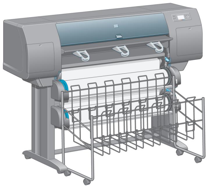
HP Designjet 4500 Printer series
Assembly Instructions
©2005 Hewlett-Packard Company
Inkjet Commercial Divisor
Avenida Graells 501
08174
All rights reserved.

invent

Q1272-90061

In case of difficulty, please consult:
Your printer's Embedded Web Server
Driver and Documentation CD
natural_image
3D rendering of a large printer with paper feeders and control panel (no visible text or symbols)1
Read these instructions carefully...
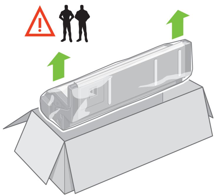
What you will need for this procedure
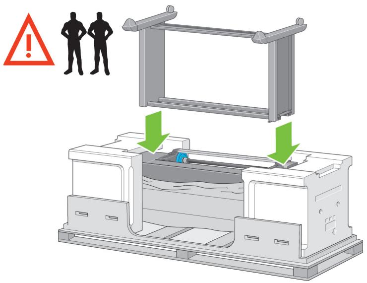
- Because some of the components of the printer are bulky, you will need up to four people to lift them. When this is necessary, this symbol is displayed:

natural_image
Four black silhouette figures standing in front of a red triangular warning sign with an exclamation mark (no text or symbols on the figures themselves)- To assemble the printer you will need at least 3 × 5 ~m (10 × 16 ft) of empty floor space, and about four hours.
natural_image
Illustration of a large printer and a paper print generator with control panel (no text or symbols visible)Scanner (mfp only)
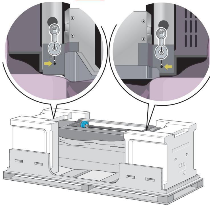
2
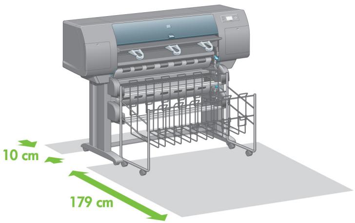
Printer working area
natural_image
3D rendering of a generic printer with green dimension annotations (10 cm and 179 cm) indicating measurement ranges, no text or symbols on the device itself.Before you start unpacking, consider where you are going to put the assembled printer. You should allow some clear space at the back and at the front of the printer. The recommended clearances are shown in the illustration above.
HP Designjet 4500 with Scanner.
If you have bought the HP Designjet 4500 with a scanner, you can reduce the overall setup time by assembling the scanner first and then switching it on. The scanner will take one hour to warm up when started for the first time.

3
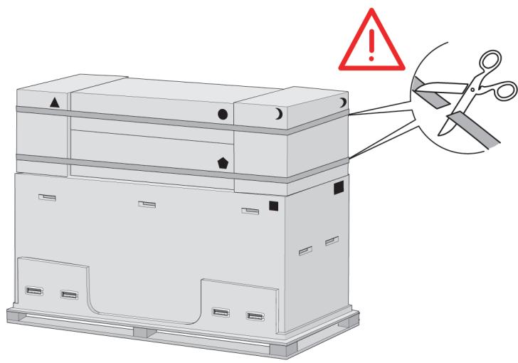
Cut the strap around the boxes carefully, as the boxes may fall as soon as the strap is cut.
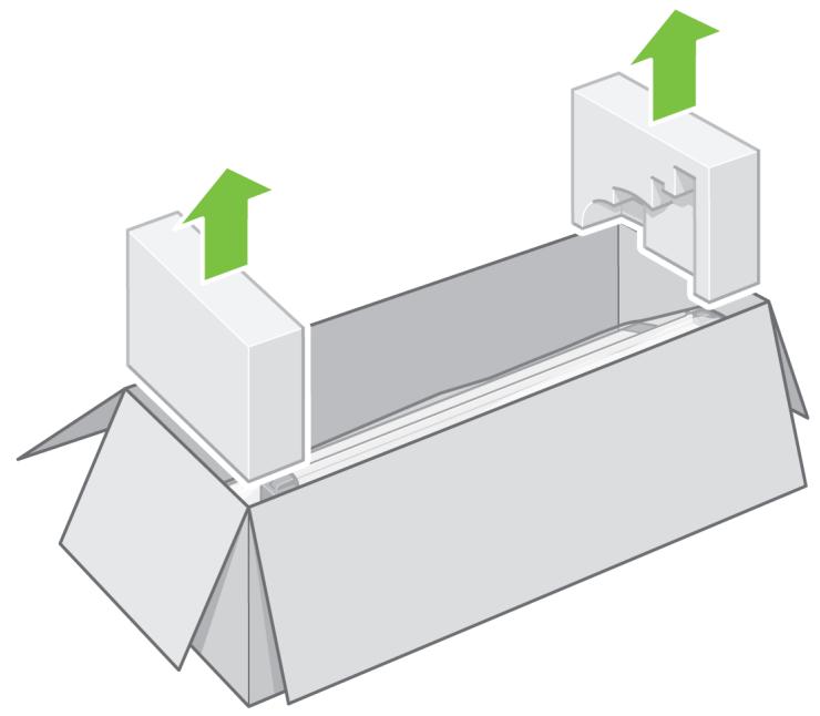
4
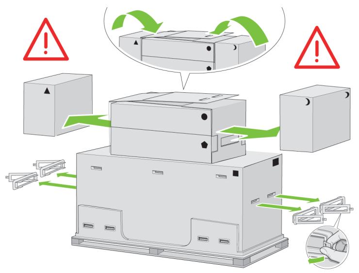
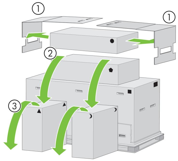
Remove all the upper four plastic handles from both sides of the box (two each side). Carefully fold the two side lids up onto the top of the box as shown, then remove the two boxes.
5
Preliminary unpacking
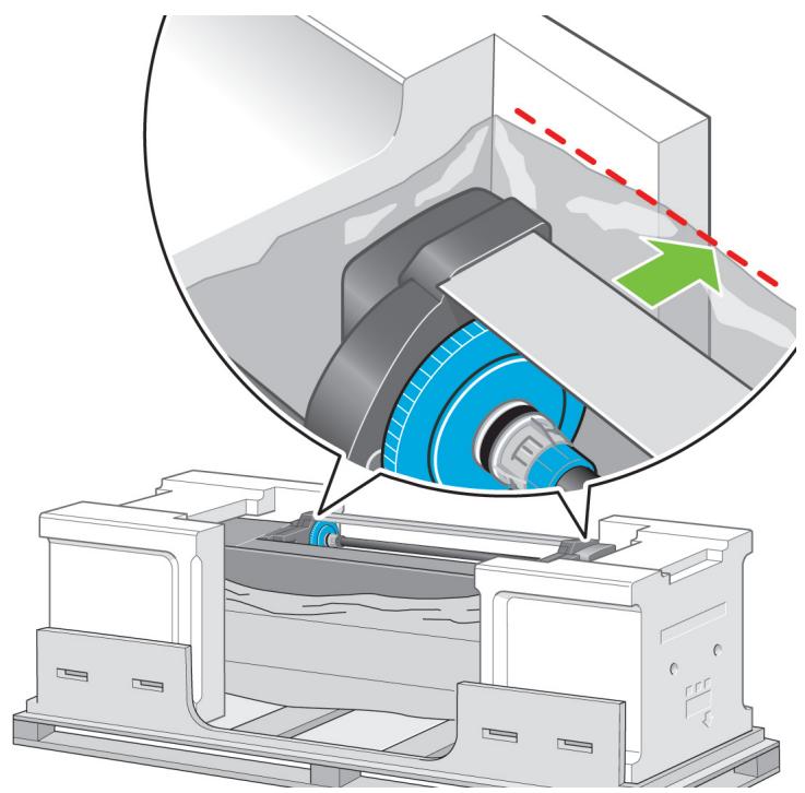
Outside Europe
natural_image
Isometric line drawing of a multi-tiered storage unit with labeled components (no text or symbols)6
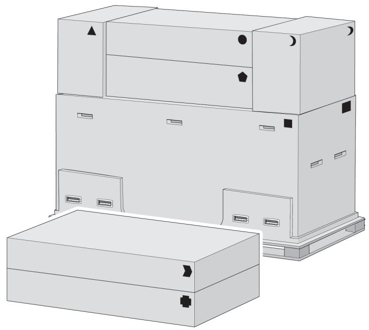
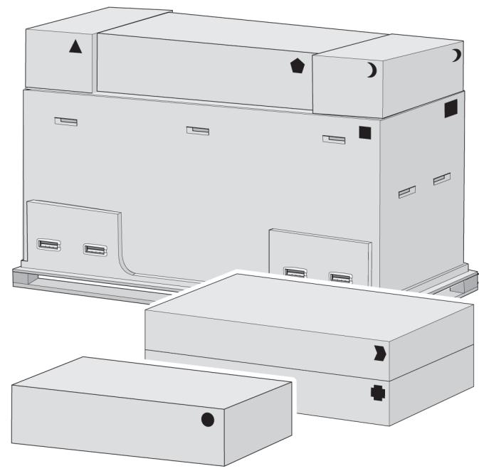
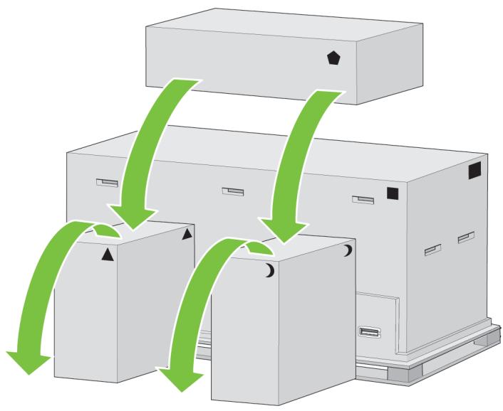
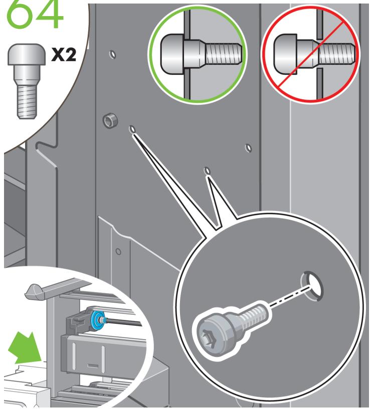
The shapes on the boxes identify the contents.
| Mark on box | Contents of box |
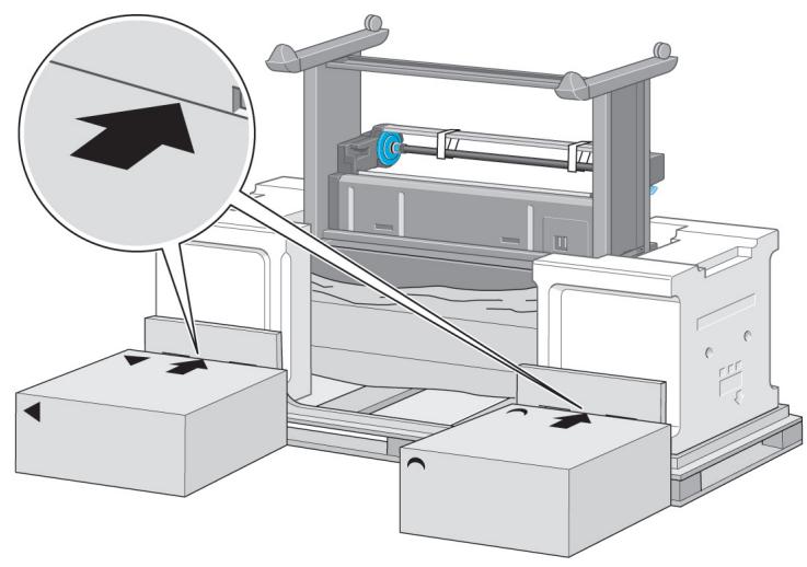
| Printer body | |
| Stand and bin assembly | |
| Consumables box, including...Maintenance Kit (please keep this safe) | |
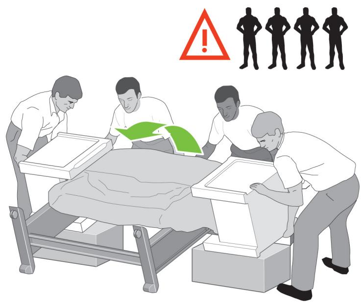
| Spare box (used on page I and J of these setup instructions) | |
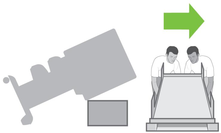
| Roll module | |
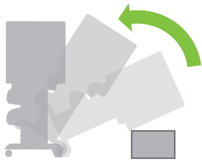
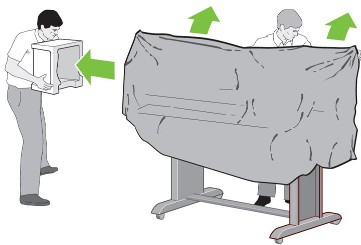
| Scanner body (mfp only) | |
| Scanner stand (mfp only) |
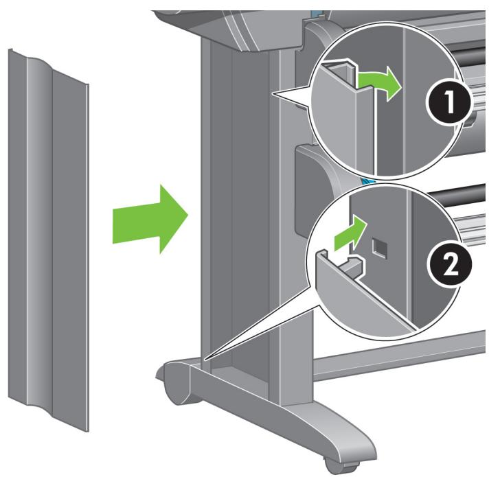
7
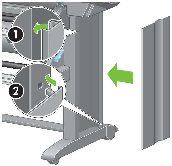
Preliminary unpacking
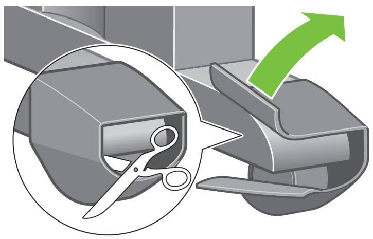
Europe
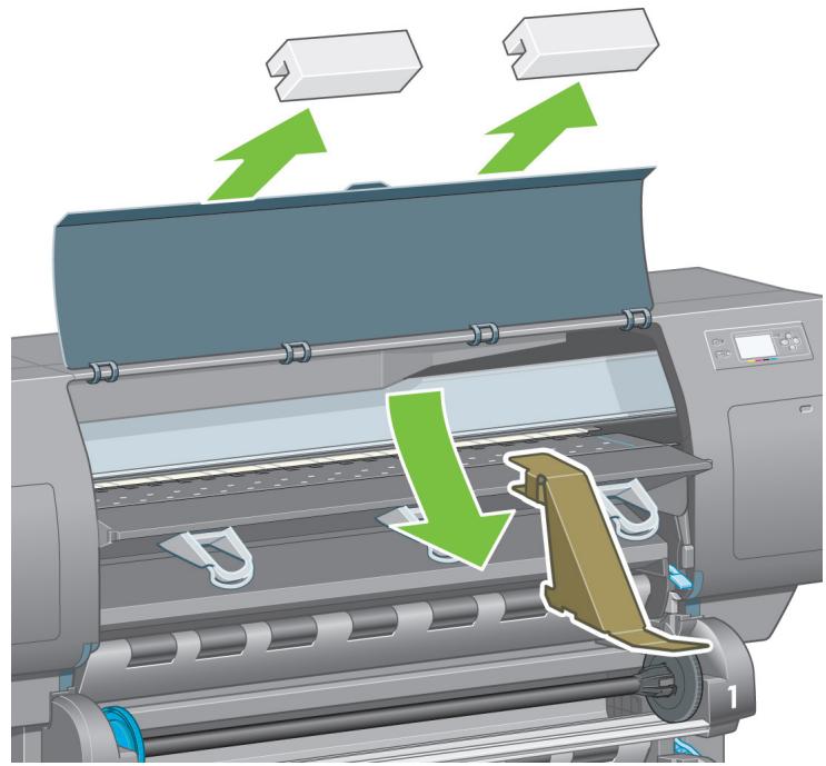
natural_image
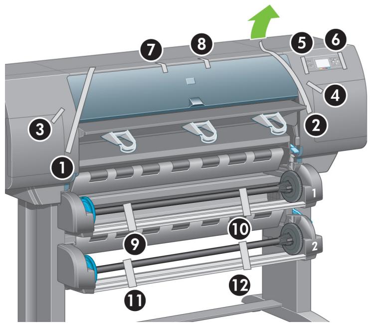
Illustration of various electronic devices with no visible text or symbols8
flowchart
graph TD
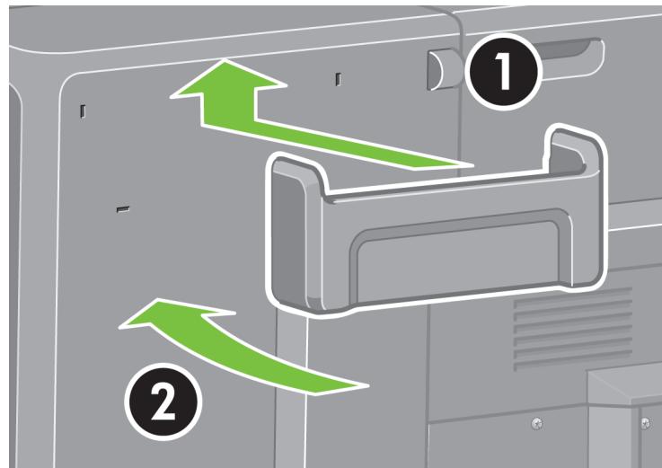
A["Step ①"] --> B["Step ②"]
B --> C["Step ③"]
C --> D["Step ④"]
Remove the 2 lids. Place the consumables and spare boxes in front of the printer body. Then lower the stand and bin box onto the consumables and spare boxes.
9
flowchart
graph TD
A["Box 1"] --> B["Box 2"]
B --> C["Box 3"]
C --> D["Box 4"]
D --> E["Box 5"]
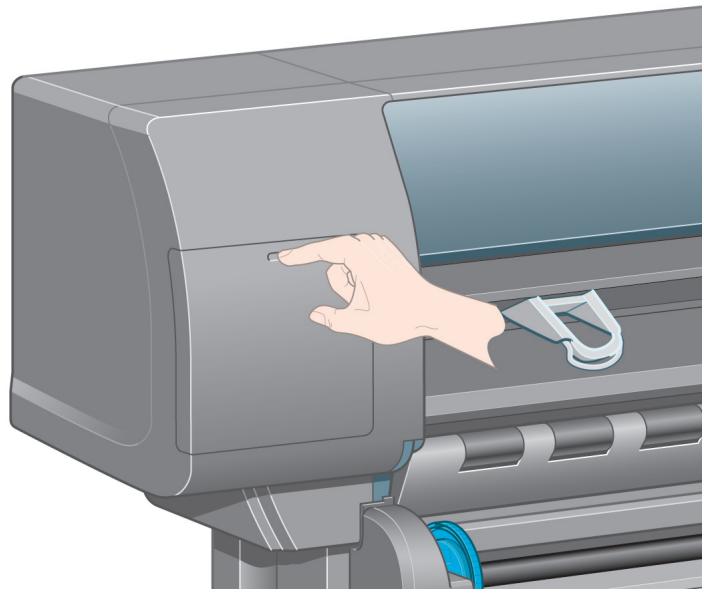
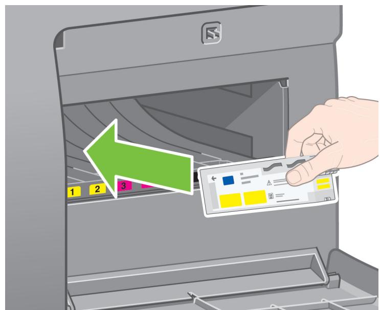
E --> F["Box 6"]
F --> G["Box 7"]
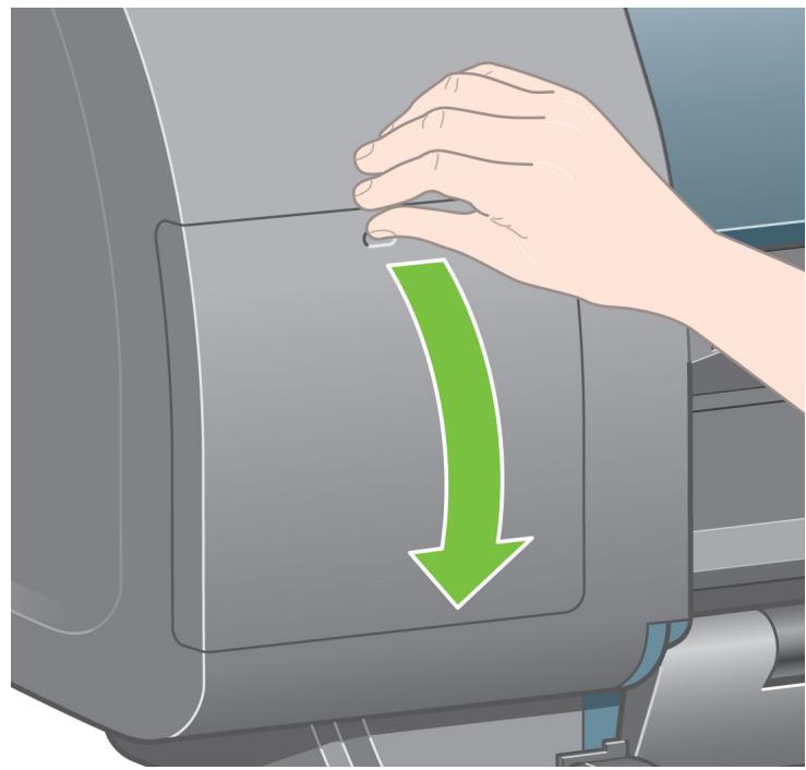
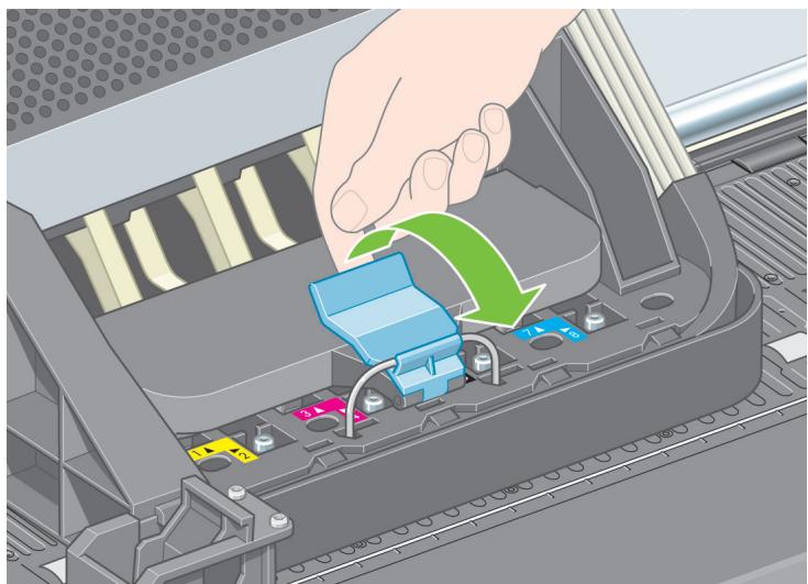
G --> H["Box 8"]
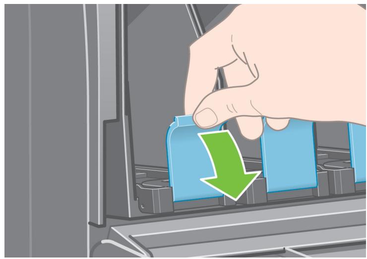
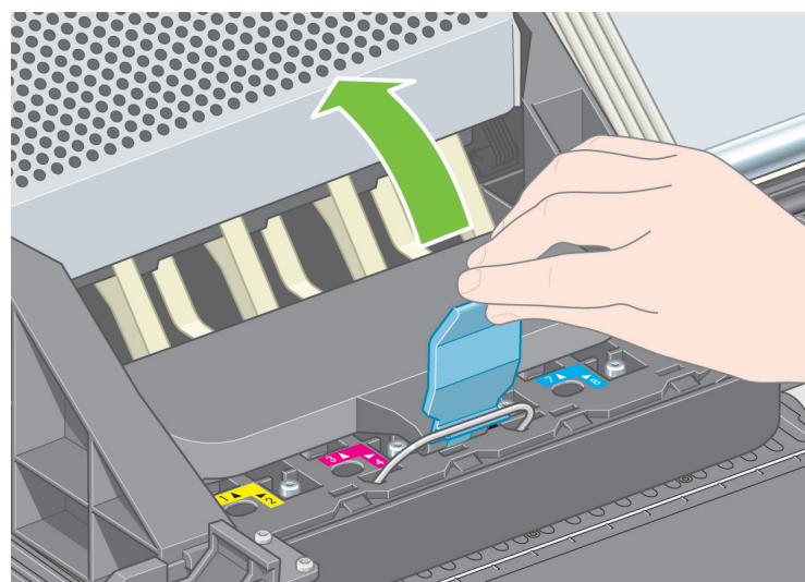
H --> I["Box 9"]
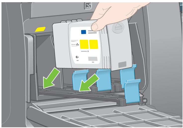
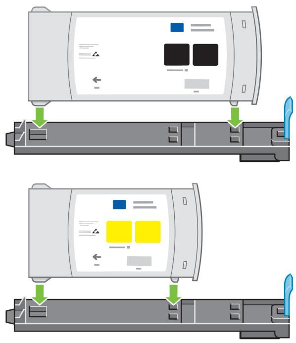
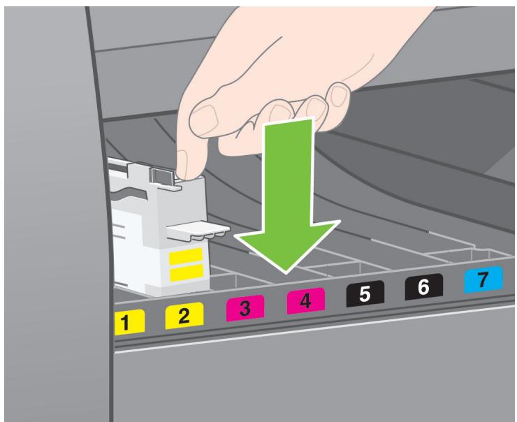
I --> J["Box 10"]
J --> K["Box 11"]
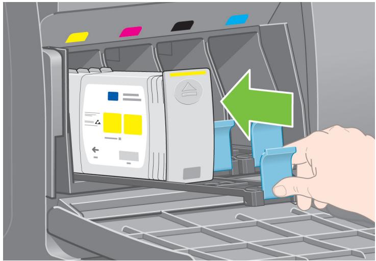
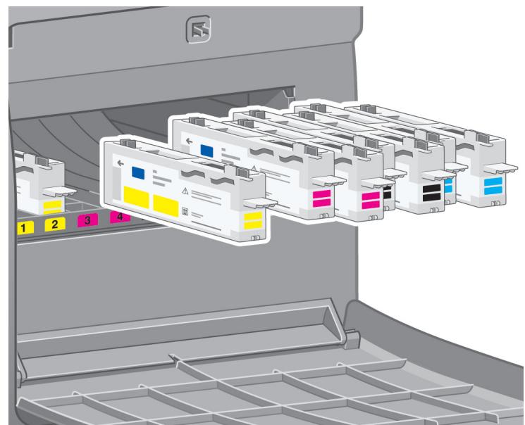
K --> L["Box 12"]
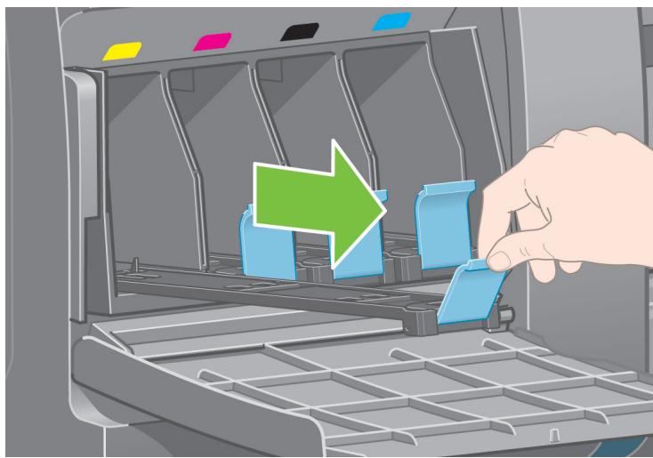
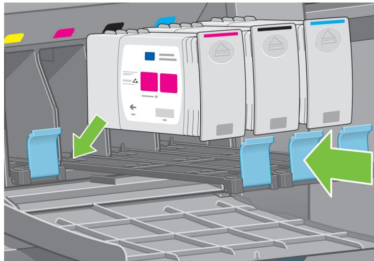
L --> M["Box 13"]
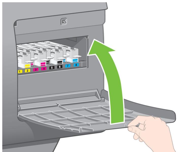
M --> N["Box 14"]
N --> O["Box 15"]
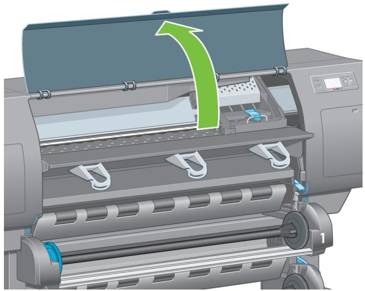
O --> P["Box 16"]
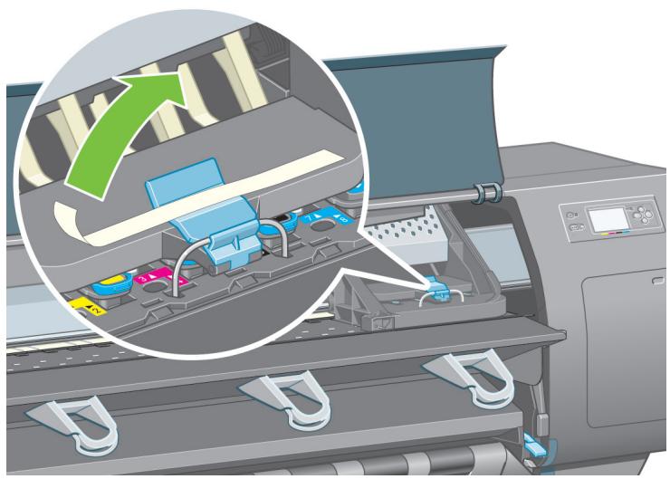
P --> Q["Box 17"]
Q --> R["Box 18"]
R --> S["Box 19"]
S --> T["Box 20"]
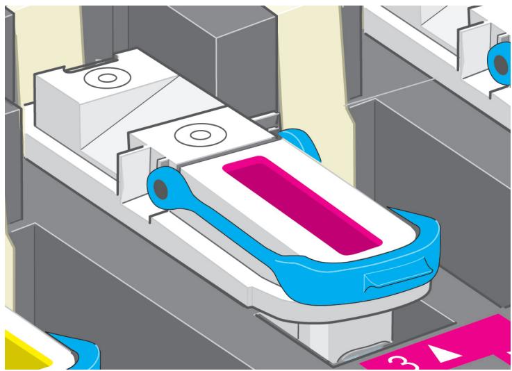
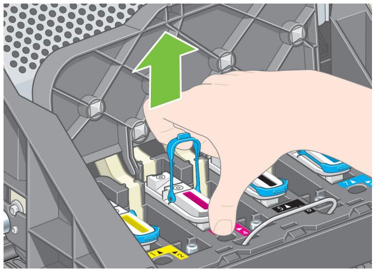
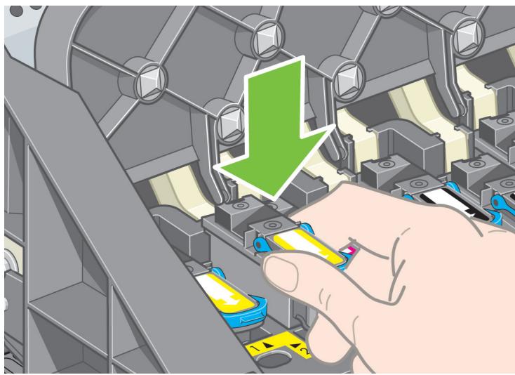
Lower the roll module box onto the consumables and spare boxes. Then lower the roll module box onto the floor. Then remove the consumables and spare boxes.
10
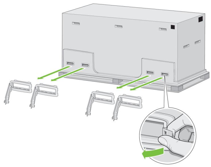
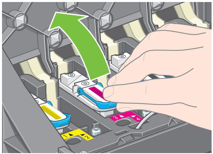
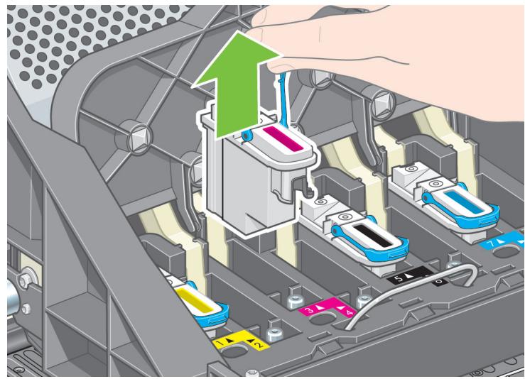
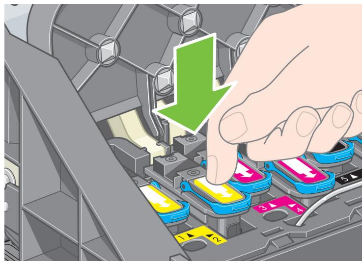
natural_image
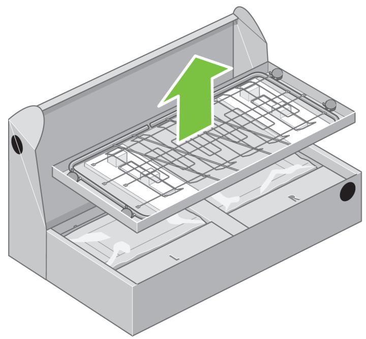
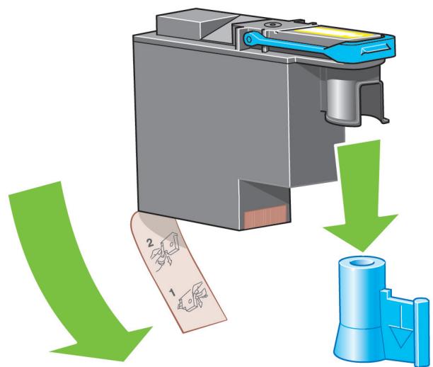
Diagram of a device with multiple connectors and a magnified inset showing a hand inserting a component into a panel (no text or symbols present)Remove all eight plastic handles from both sides of the box.
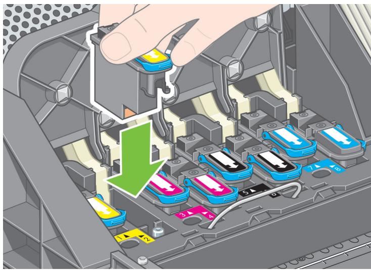
11
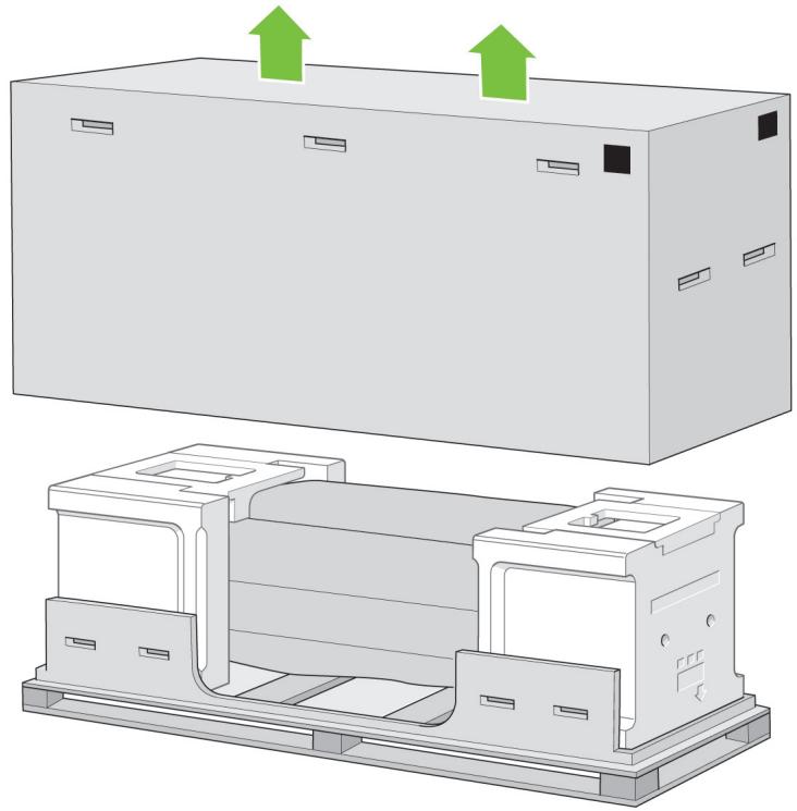
natural_image
Technical illustration of a mechanical assembly with two views: top shows a rectangular housing with green arrows indicating upward motion, bottom shows a multi-layered internal structure with cutouts and mounting brackets (no text or symbols)Remove the main printer box.
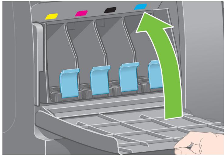
B
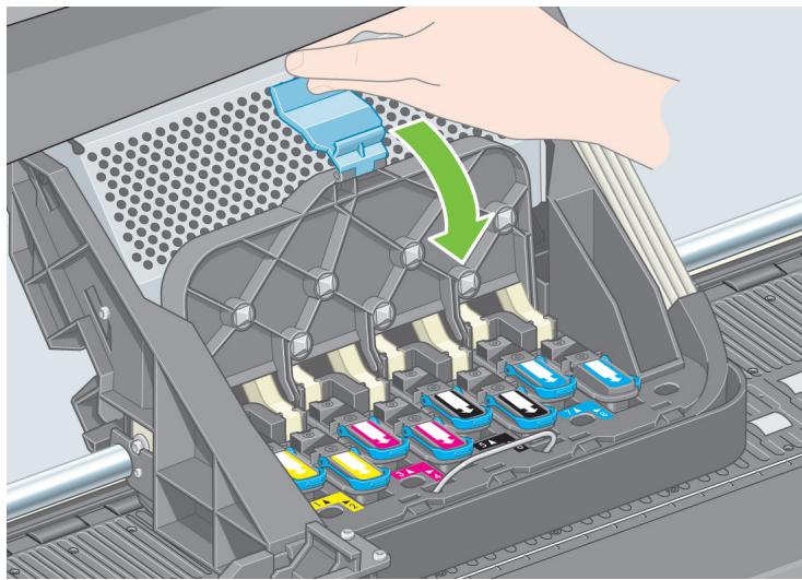
12
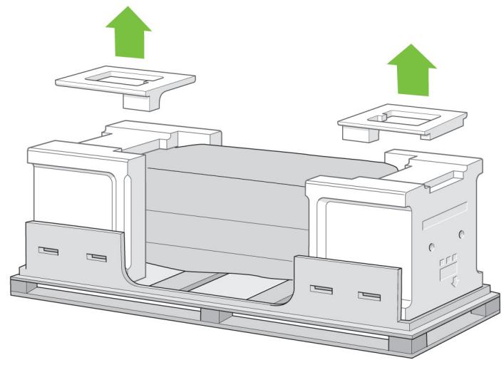
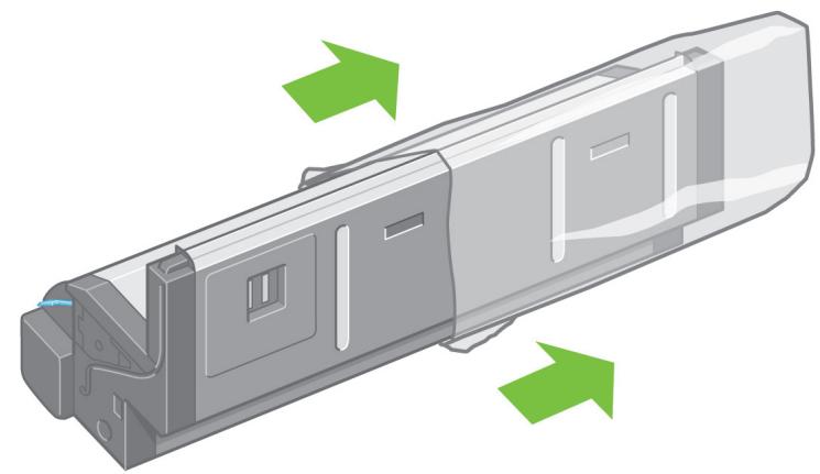
natural_image
3D diagram of a mechanical assembly with green arrows indicating upward motion (no text or symbols)Remove the two packing pieces.
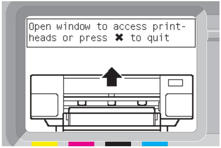
13

When you are unpacking the stand assembly, you will see that there is anti-slip material around two of the wheels on the feet. DO NOT REMOVE this material yet.
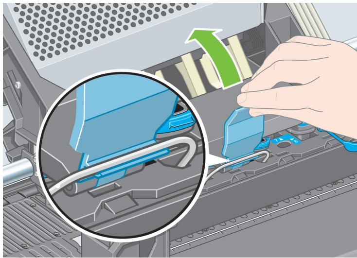
14
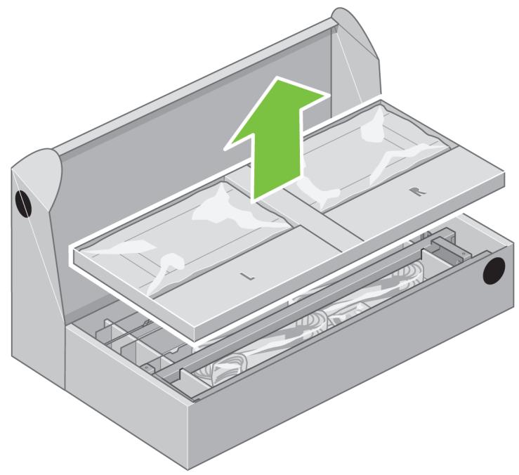
natural_image
3D illustration of a kitchen appliance with a green upward arrow indicating growth or direction (no text or symbols)Remove the first tray containing the parts for the bin.
15
natural_image
3D illustration of a mechanical device with internal compartments and a green upward arrow indicating flow or movement (no text or symbols)Remove the second tray from the stand and bin assembly box. This tray contains the stand legs.
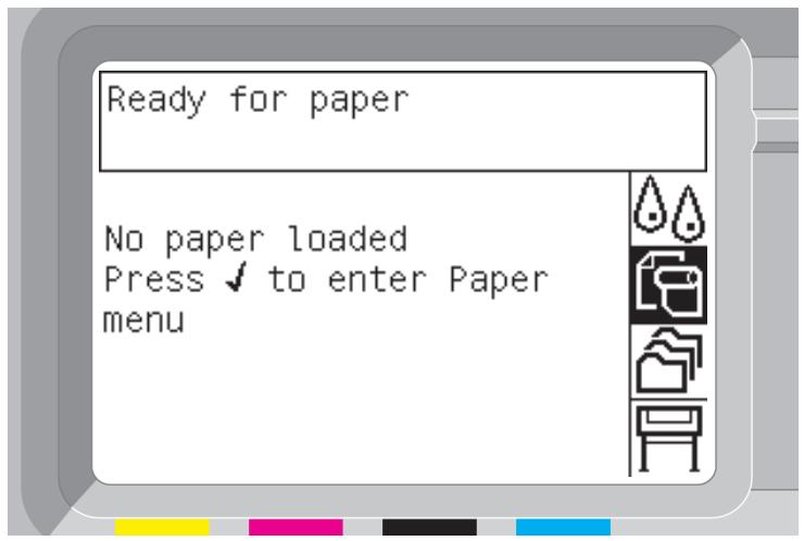
16
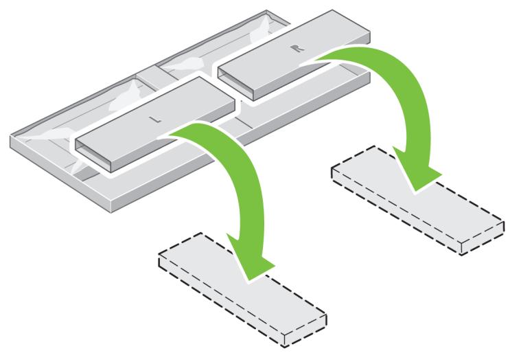
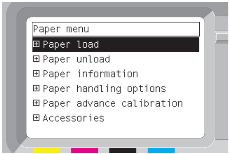
flowchart
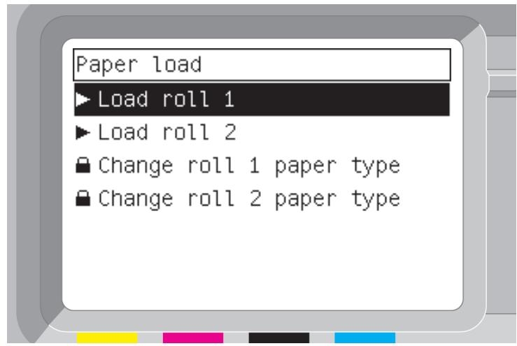
graph TD
A["Rectangular Block L"] --> B["Rectangular Block R"]
B --> C["Terminal Block"]
C --> D["Terminal Block"]
style A fill:#f9f,stroke:#333
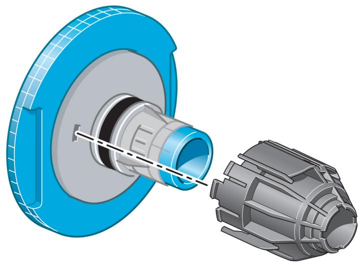
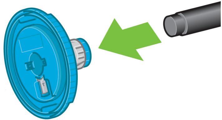
style B fill:#f9f,stroke:#333
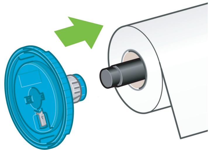
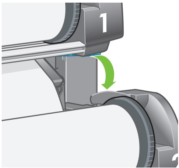
style C fill:#f9f,stroke:#333
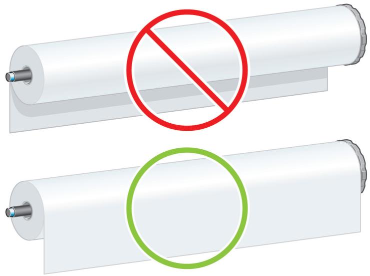
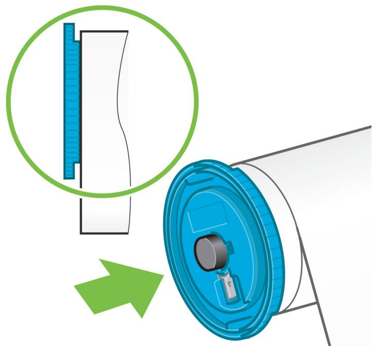
style D fill:#f9f,stroke:#333
From the second tray, remove the two boxes marked with L and R. Place them on the floor as shown.
17
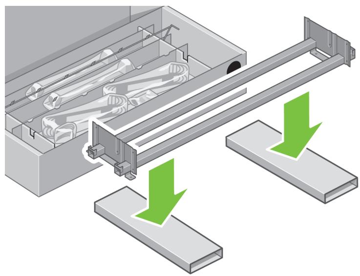
natural_image
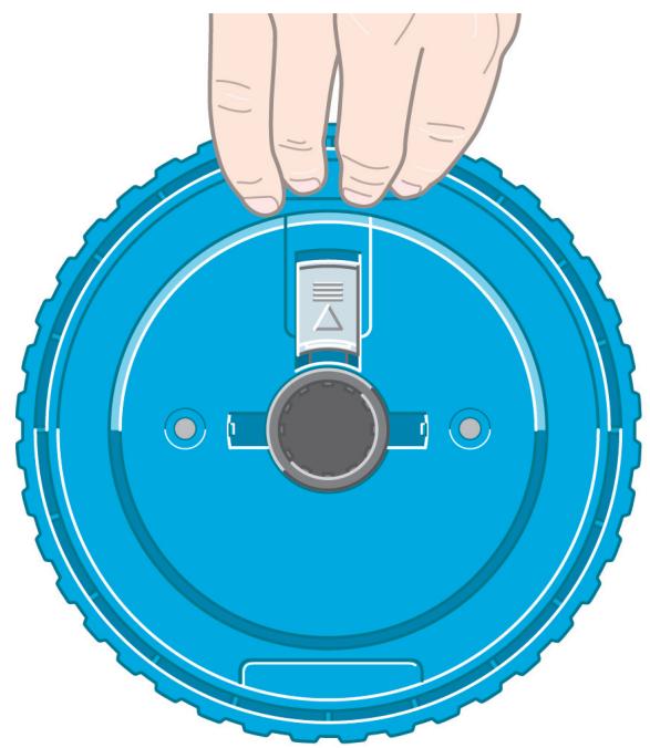
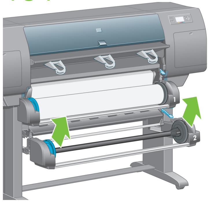
Diagram of a mechanical assembly with green arrows indicating downward motion, showing internal components and support structures (no text or symbols)Lower the cross-brace on to the L and R boxes.
18
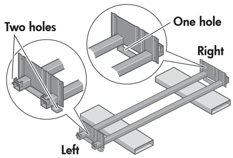
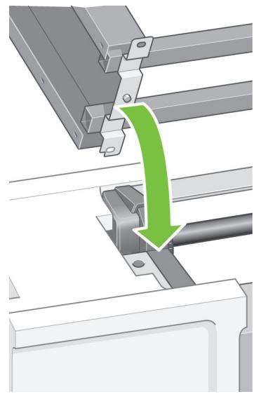
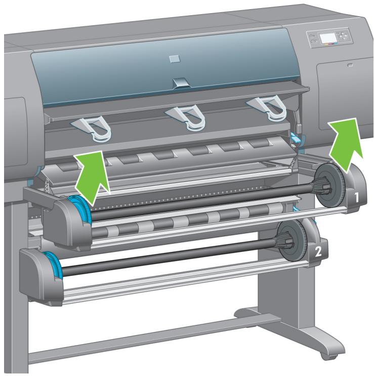
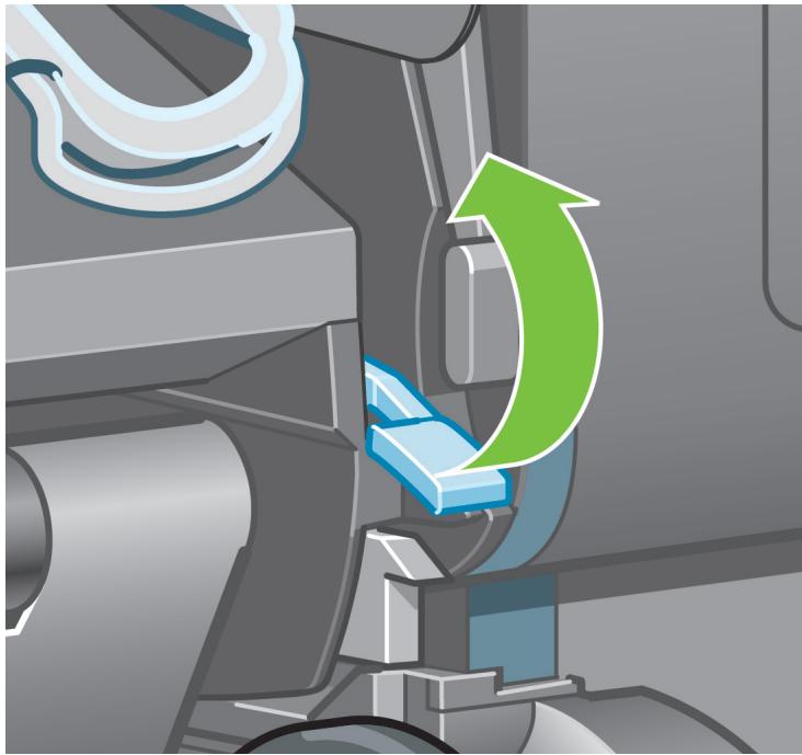
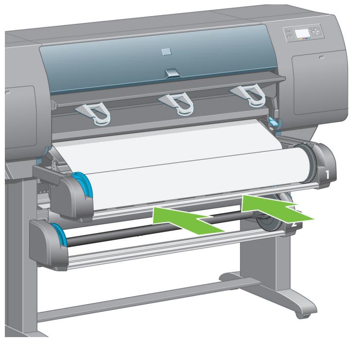
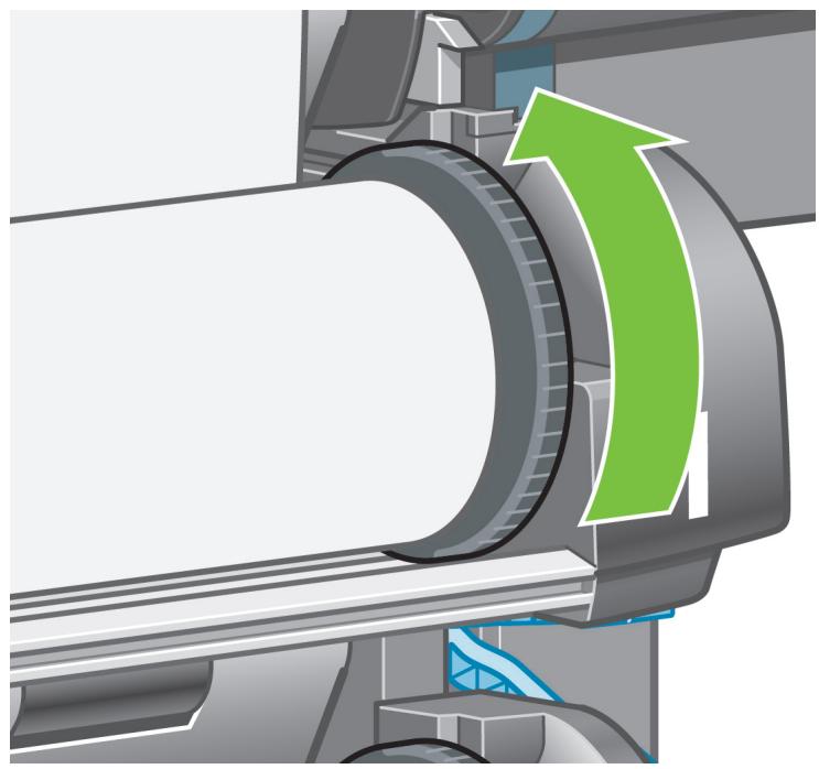
You now need to identify which is the left and the right side of the cross-brace.
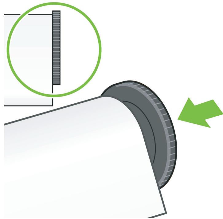
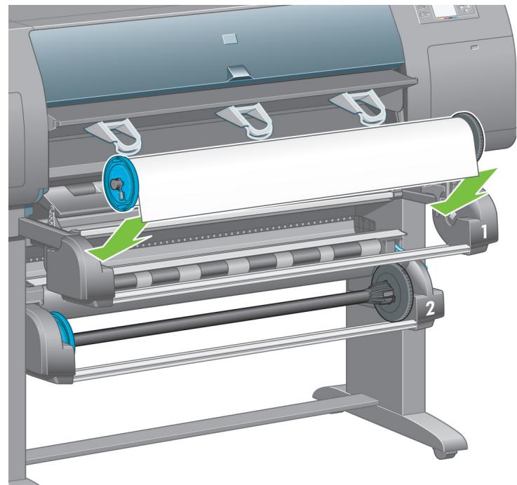
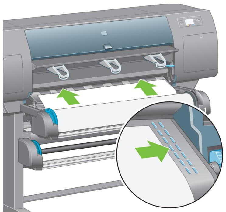
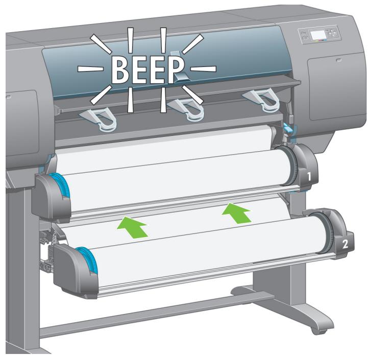
C
19
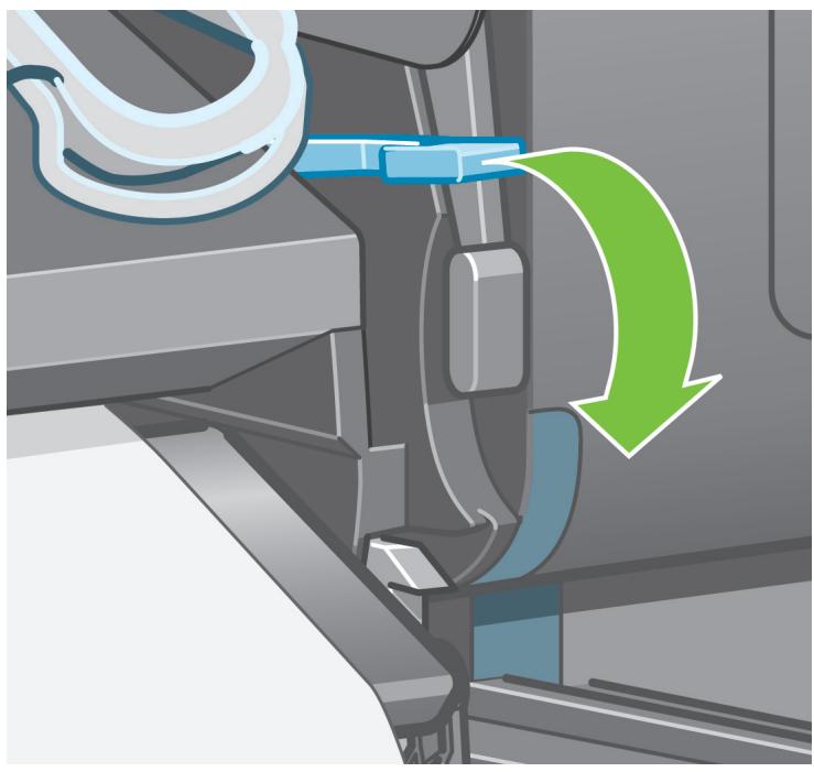
natural_image
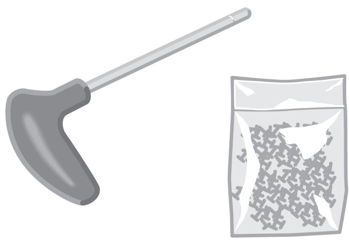
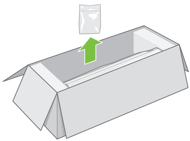
Illustration of a hand holding a long-handled tool next to a bag filled with granular material (no text or symbols)Now you will need the bag of screws and the screwdriver provided. You may notice that the screwdriver is slightly magnetic.
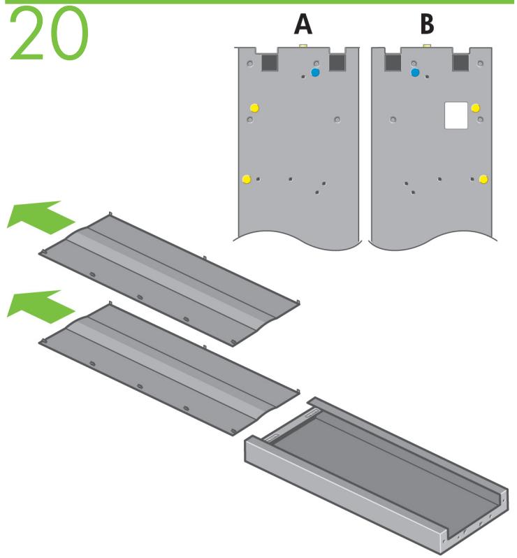
Identify the left leg (A) and the right leg (B) as shown above. Remove the two leg covers from the left leg.
21
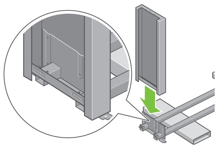
natural_image
Technical illustration of a metal frame assembly with a green arrow indicating a component or process (no text or symbols present)Lower the left leg onto the left side of the cross-brace. The left leg will fit only on the left side of the cross-brace.
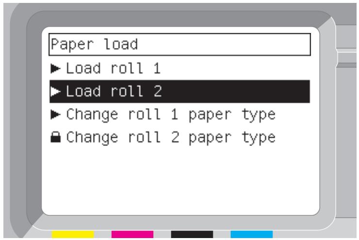
22
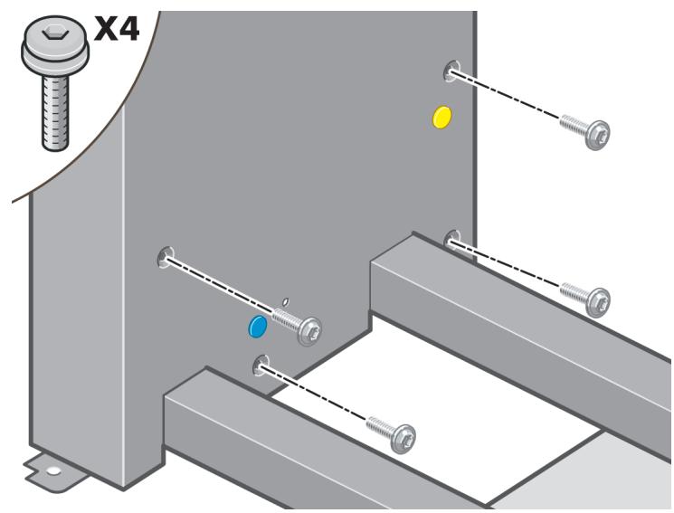
natural_image
Mechanical assembly diagram showing a bolt and four screws mounted on a metal bracket (no text or symbols)Fix the left leg to the cross-brace using four screws on the inner side of the leg.
23
Fix the left leg to the cross-brace using two screws on the outer side of the leg.
24
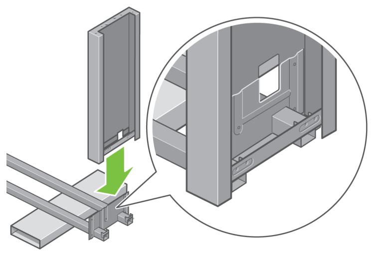
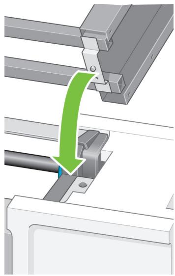
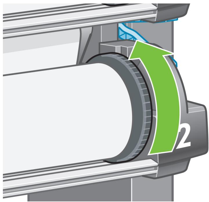
natural_image
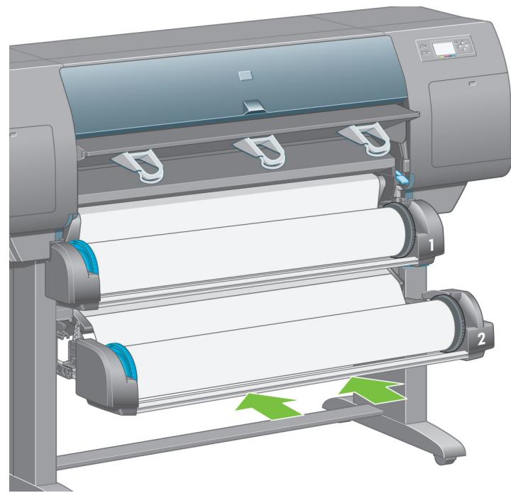
Technical illustration of a mechanical assembly with a green arrow indicating a component, showing no text or symbols.Lower the right leg onto the right side of the cross-brace. The right leg will fit only on the right side of the cross-brace.
25
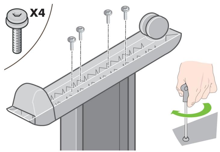
Fix the right leg to the cross-brace using four screws on the inner side of the leg.
26
Fix the right leg to the cross-brace using two screws on the outer side of the leg
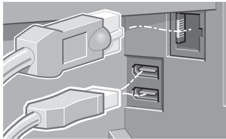
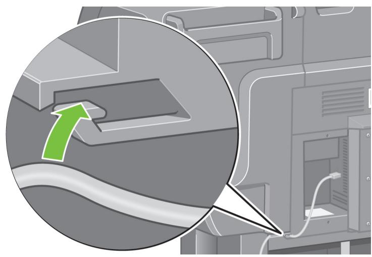
D
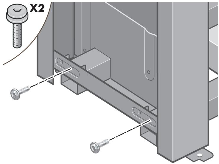
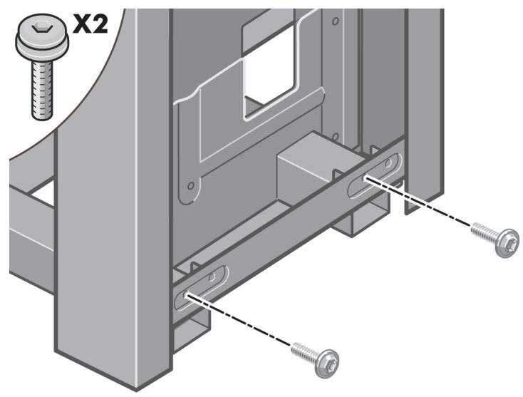
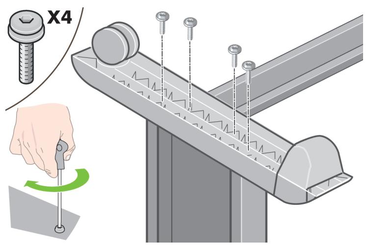
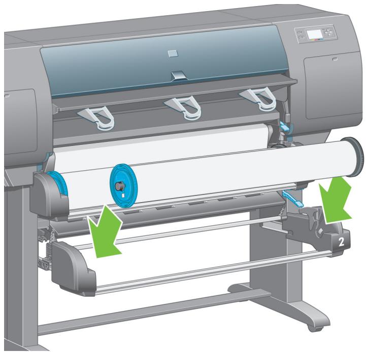
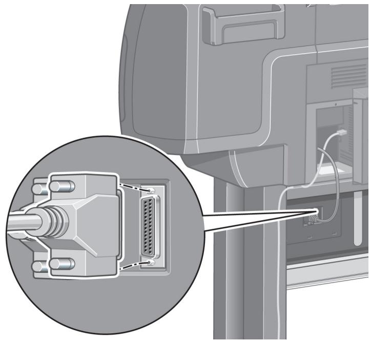
27
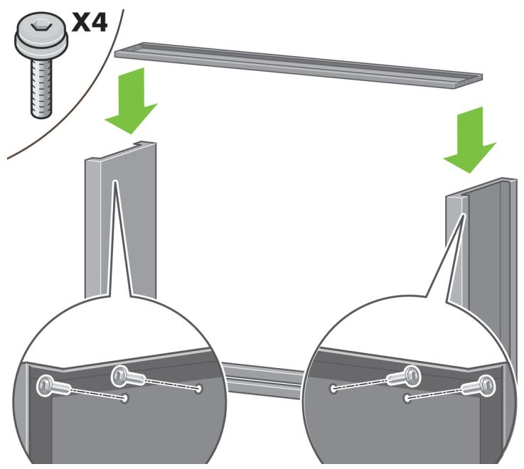
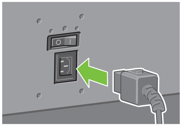
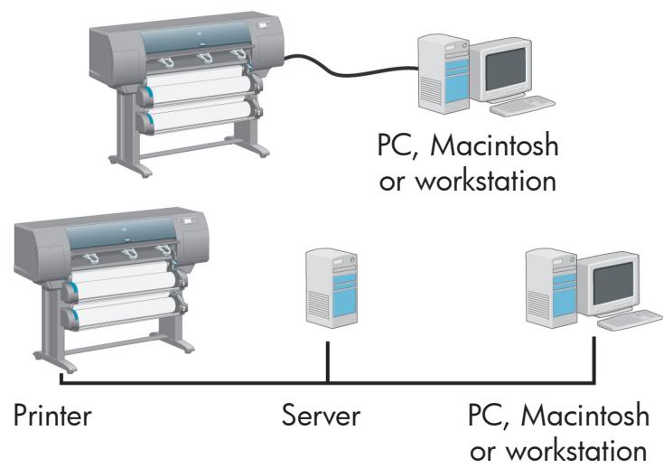
Fix the stand cross-bar using four screws.
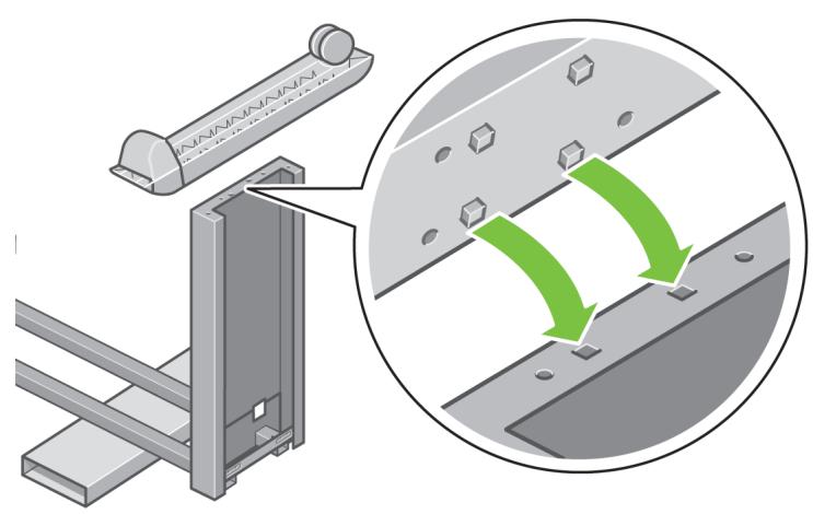
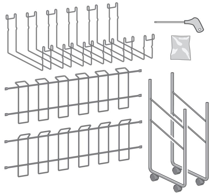
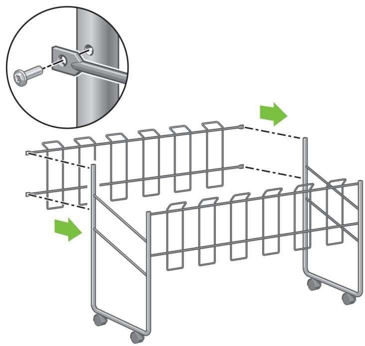
28
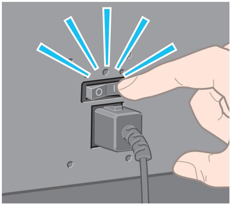
natural_image
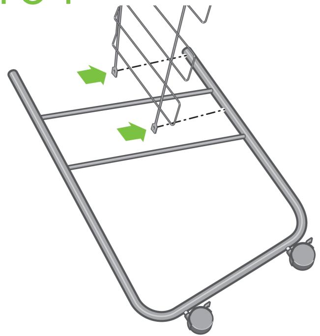
Diagram showing a mechanical assembly with green arrows indicating motion or force direction (no text or symbols present)Position a foot on the left leg. There are pins to help you to position the foot correctly. Do not remove the anti-slip material from the wheel.
29
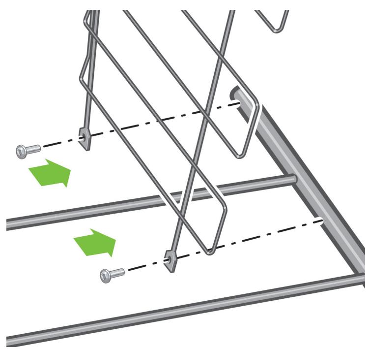
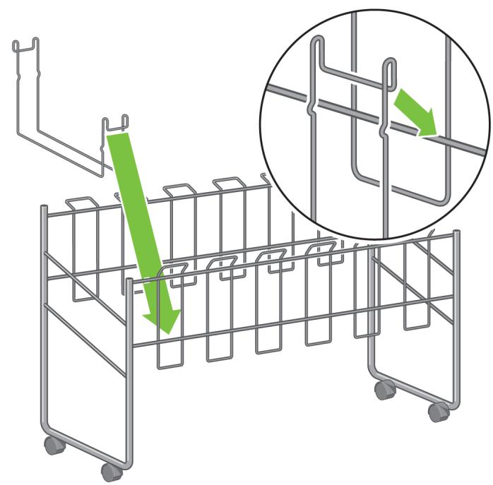
Fix the left foot using four screws.
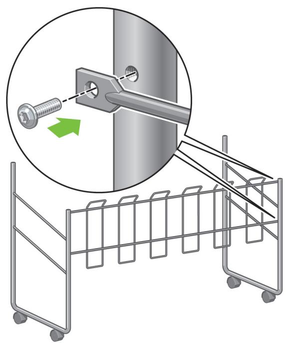
30
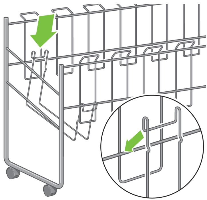
natural_image
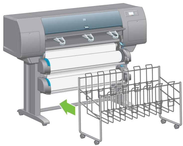
Technical diagram showing a metal bracket assembly with an inset illustrating the process of alignment or reassembly (no text or symbols present)Position a foot on the right leg. There are pins to help you to position the foot correctly. Do not remove the anti-slip material from the wheel.
31
Fix the right foot using four screws.
32
natural_image
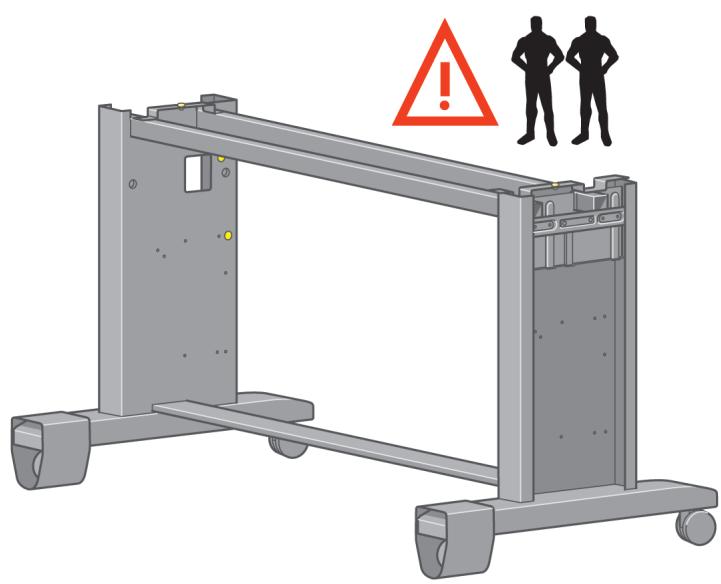
3D rendering of a mechanical frame with two silhouettes and an exclamation mark (no text or symbols on the frame itself)Turn the stand assembly into an upright position as shown above.
33
natural_image
Illustration of a cardboard box with a green upward arrow pointing to it, no text or symbols present.Open the box containing the roll module. Remove the plastic bag containing the screws.
34

natural_image
Diagram of a container with colored dots and screw holes, no text or symbols presentLeft leg
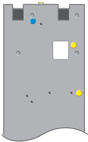
natural_image
Diagram of a gray electronic device casing with multiple ports and colored circular markers (no text or symbols)Right leg
Please take note of the colored plugs located on the legs.
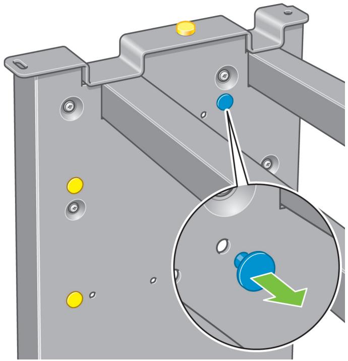
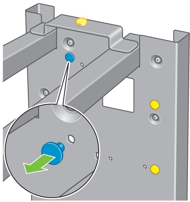
35
natural_image
Mechanical assembly diagram showing a metal bracket with bolt holes and a magnified inset highlighting a blue-green button (no text or symbols)Remove the blue plug on the left leg.

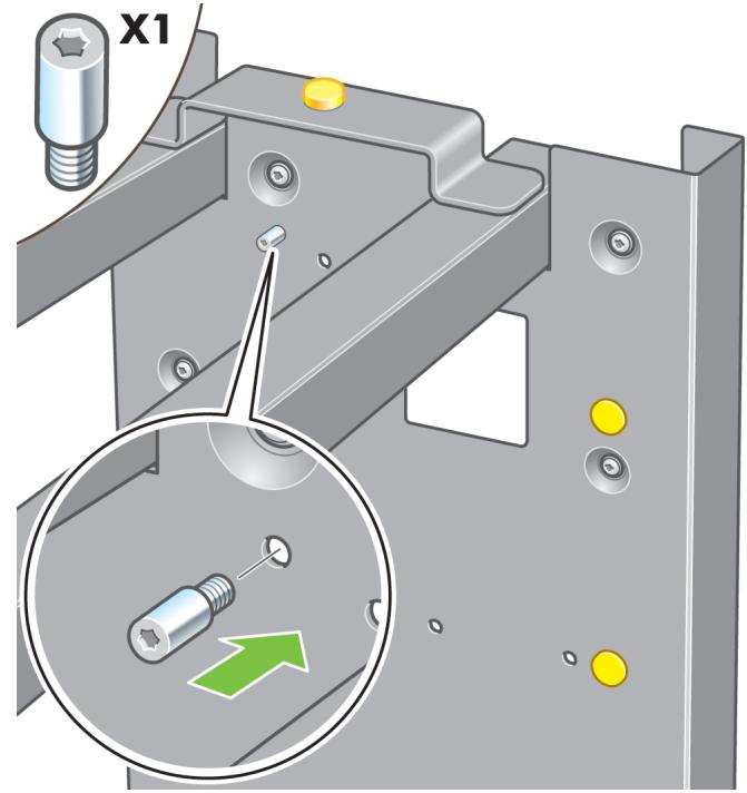
36
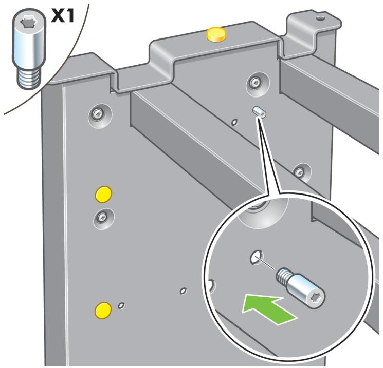
Locate the pin into the left leg.
37
natural_image
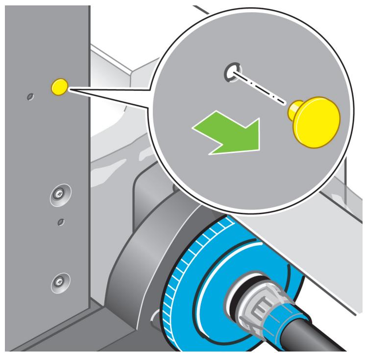
Mechanical assembly diagram showing a bracket with mounting holes and a magnified inset highlighting a green arrow (no text or symbols)Remove the blue plug on the right leg.
38
Locate the pin into the right leg.
39
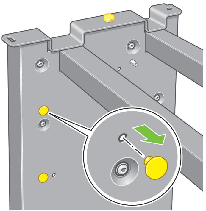
natural_image
Mechanical assembly diagram showing a metal bracket with yellow circular components and a magnified inset highlighting a green arrow pointing to a specific component (no text or symbols present)Remove the top yellow plug on the left leg.
40
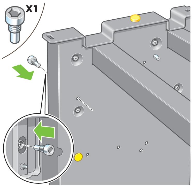
Locate the pin into the interior of the left leg.
41
natural_image
Mechanical assembly diagram showing a bracket with yellow components and a magnified inset highlighting a key mechanism (no text or symbols present)Remove the top yellow plug on the right leg.
42
Locate the pin into the interior of the right leg.
43
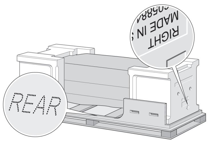
You now need to identify the left and right of the printer. This information is shown on the foam end packs. Also identify the rear of the printer.
44
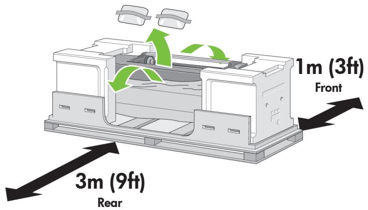
Pull open the protective plastic from the base of the printer.
Please ensure that there is a three-meter space clear of obstructions to the rear of the printer and one meter at the front of the printer.
Remove the two desiccant bags from the printer.
45

Do not reinsert these screws after removal!
natural_image
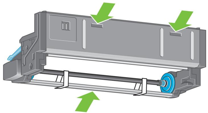
Technical illustration of a mechanical assembly with two circular insets showing close-ups of mechanical components (no text or symbols present)Using the screwdriver supplied, remove the two screws that hold Drawer 1 in place. Note: the screws are only for transit, they are not to be replaced.
46
natural_image
Technical illustration of a mechanical assembly with a magnified inset showing internal components and a green arrow indicating direction (no text or symbols present)Slide Drawer 1 out until it touches the foam packaging.
47
Left leg.
natural_image
Mechanical assembly diagram showing a bracket being inserted into a rail, with a green arrow indicating the process (no text or symbols present)Right leg.
natural_image
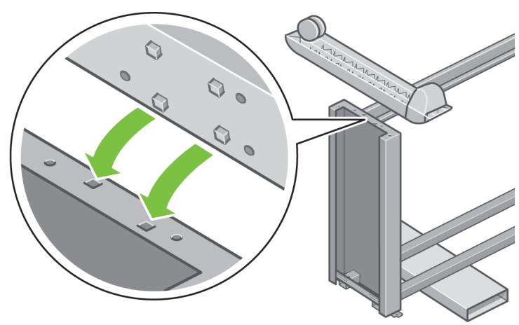
Mechanical assembly diagram showing a green arrow indicating a process or operation, with no visible text or symbols.Advance warning: in the next step, make sure you position the stand pins in the holes in the center of the printer body brackets.

48
Lift the stand assembly onto the printer body.
The anti-slip material should face to the rear of the printer.
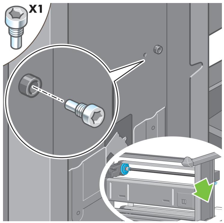
49
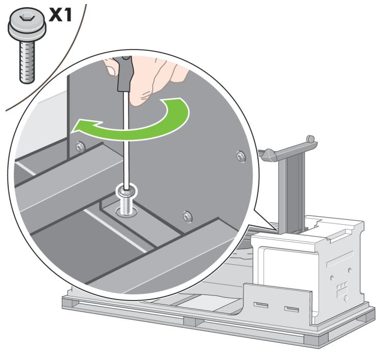
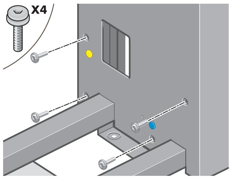
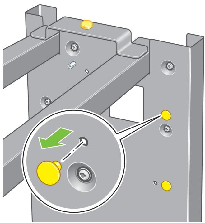
Fix the right side of the stand to the printer using one screw. Make sure that the screw is fully tightened.
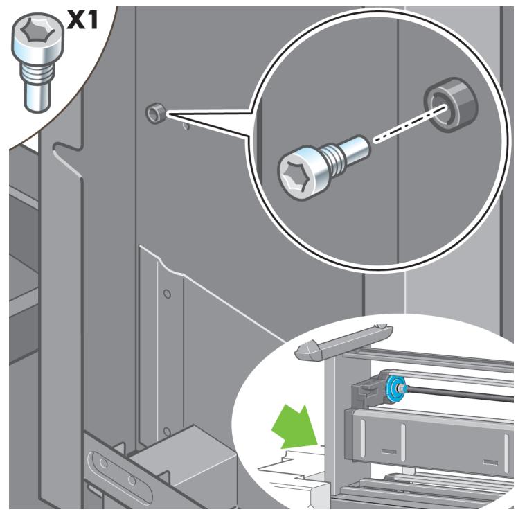
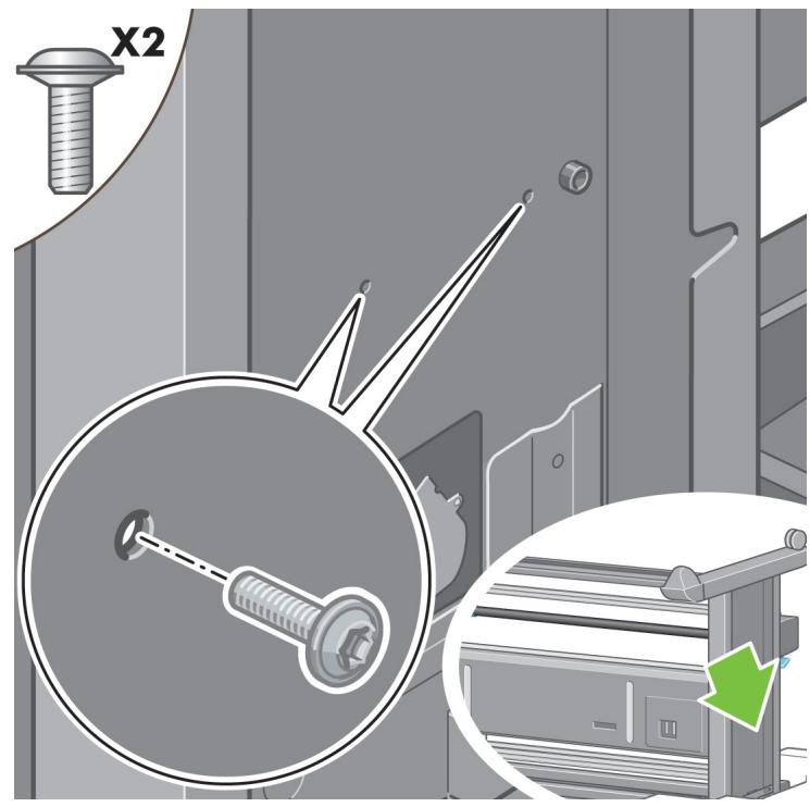
50
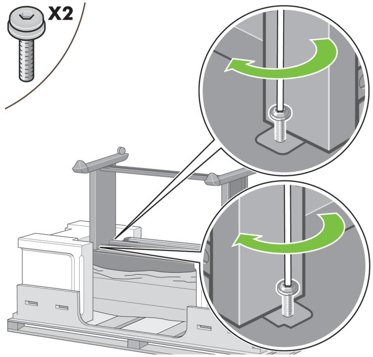
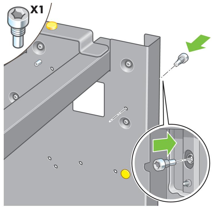
Slide Drawer 1 forwards to gain better access for the front screw. Fix the left side of the stand to the printer using two screws. Make sure that the screws are fully tightened.
51
Important information
natural_image
3D diagram of a printer or printer casing with green arrows indicating directional movement (no text or symbols)Before unpacking the roll module, note that you should only handle this piece of equipment using the points indicated by the green arrows shown above.

52
natural_image
3D diagram of a mechanical assembly with green arrows indicating upward motion (no text or symbols)Open the box containing the roll module, then remove the two foam supports.
53
natural_image
Illustration of a car interior with two silhouettes and warning symbols (no text or labels)Remove the roll module from the packaging box.
54
natural_image
3D diagram of a mechanical component with green arrows indicating directional flow or movement (no text or symbols)Remove the roll module from the plastic bag.
55
natural_image
Mechanical assembly diagram showing a blue gear and a yellow knob with a green arrow indicator (no text or symbols)Remove the remaining two yellow plugs from the left and right legs. It is important to remember the positions of these holes.
56
natural_image
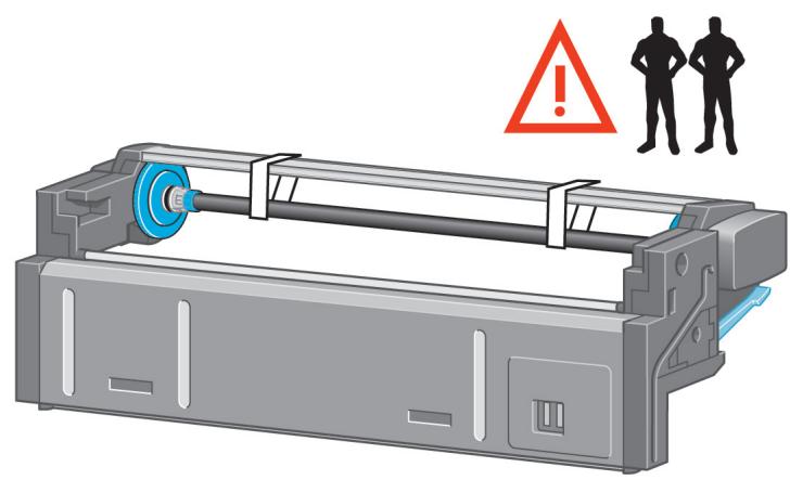
Illustration of a printer with warning symbol and two silhouettes, no text or symbols presentTurn the roll module over into an inverted position as shown above. Then carry it to the front of the inverted printer.
57
Rest the roll module next to the first printer crossbar.
58
natural_image
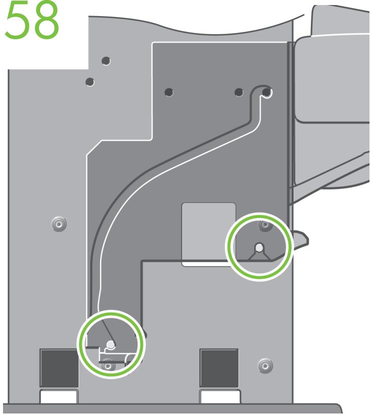
Technical diagram of a mechanical assembly with highlighted components (no text or symbols)Before the roll module is moved into its final position, please note that the roll module should sit on the pins that were located on the stand legs earlier.

59
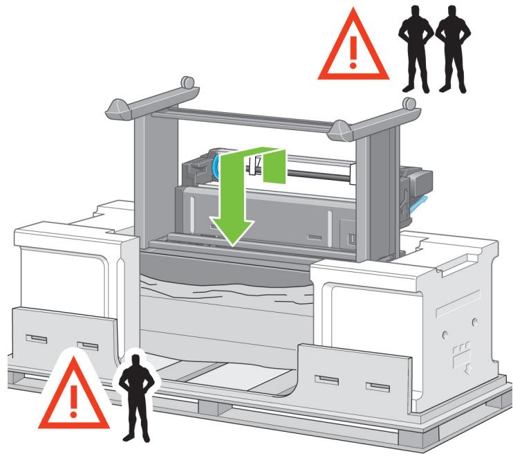
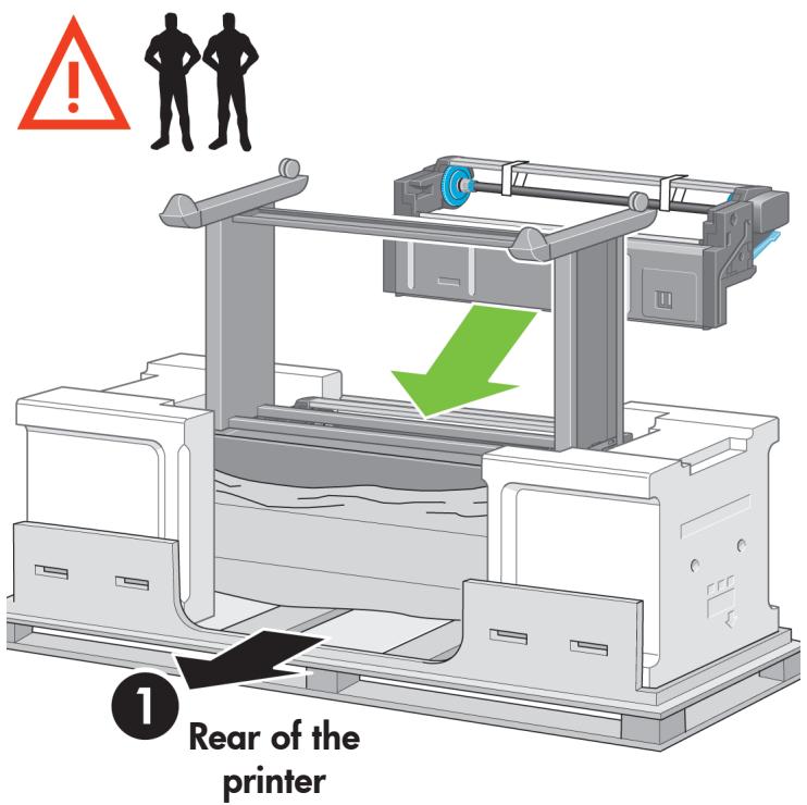
Three people are needed, two at the front and one at the rear of the printer. The two at the front should lift the roll module and then, with the help of the third person at the rear, lower it vertically onto the pins located earlier on the stand."
60
natural_image
3D rendered mechanical component with a green circular highlight (no text or symbols)Look at the front of the roll module and check that it comes close to the legs of the stand
61
Fix the roll module to the right leg of the stand.
62
Fix the roll module to the left leg of the stand.
63
Fix the roll module to the right leg of the stand using two additional screws.
64
Fix the roll module to the left leg of the stand using two collar-headed screws.
65
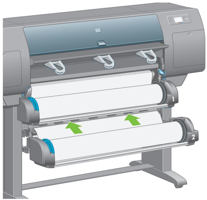
natural_image
Diagram of a printer setup with an open box and paper holder, showing mechanical components and directional arrows (no text or symbols)Place the spare and consumables boxes against the rear of the printer box. The arrows on the boxes must point towards the printer box. Check that the anti-slip material is still fixed to the two rear wheels.
66

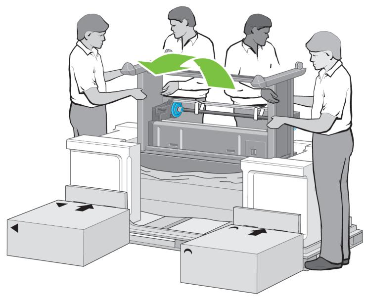
natural_image
Illustration of workers operating industrial machinery with green arrows indicating process flow (no text or symbols)Using four people, rotate the printer on to the spare and consumables boxes.
67
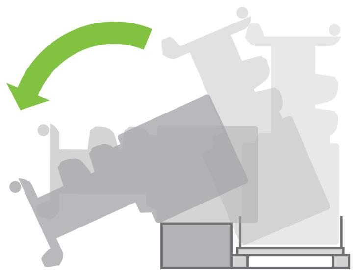
natural_image
Abstract graphic with green curved arrow and gray geometric shapes (no text or symbols)Rotate the printer until its rear rests on the spare and consumables boxes and the wheels with the anti-slip material touch the floor.
68
natural_image
Illustration showing a vehicle and two people on a treadmill, with a green arrow pointing upward (no text or symbols)Remove the pallet before trying to lift the printer into an upright position.
69
natural_image
Illustration of medical staff attending to a patient in a hospital bed, with silhouettes and a warning symbol above (no text or labels)Using four people and the hand holds on the rear of the printer body, carefully lift the printer into an upright position.
70
natural_image
Abstract graphic with overlapping gray shapes and a green curved arrow, no text or symbols presentRotate the printer into an upright position. The anti-slip material should stop the printer from sliding forwards.
71
natural_image
Illustration showing two people handling a large gray object next to a person holding a box, with green arrows indicating direction (no text or symbols present)Remove the two foam end packs and the plastic covering the printer.
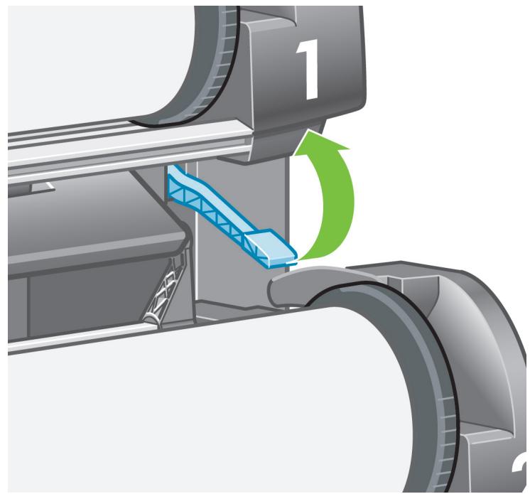
72
Position the left leg cover on the front of the left leg (1), then clip the rear edge (2) into place.
73
Position the right leg cover on the front of the right leg (1), then clip the rear edge (2) into place.
74
natural_image
Illustration of a mechanical device with scissors cutting through a slot, showing a green upward arrow (no text or symbols)Remove the anti-slip material from the two rear wheels on the stand assembly.
75
Remove the packing tapes 1 to 12.
J
76
natural_image
Illustration of a printer with green arrows indicating process flow, showing paper roll and printer blade (no text or symbols)Open the printer window. Then remove the two window inserts and the ink tube packing material.
77
natural_image
Illustration of a printer with a green arrow indicating motion, showing internal components and a magnified view (no text or symbols)Remove the protective covering from the printer window and the front panel screen.
78
Open the printhead cleaner door and remove the carriage packing material. Then close the cleaner door.
79
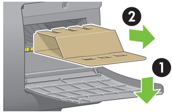
Install the Quick Reference Guide holder. Angle the holder at the top (1), then position the two hooks and clip the lower part (2) to the rear of the printer.
80
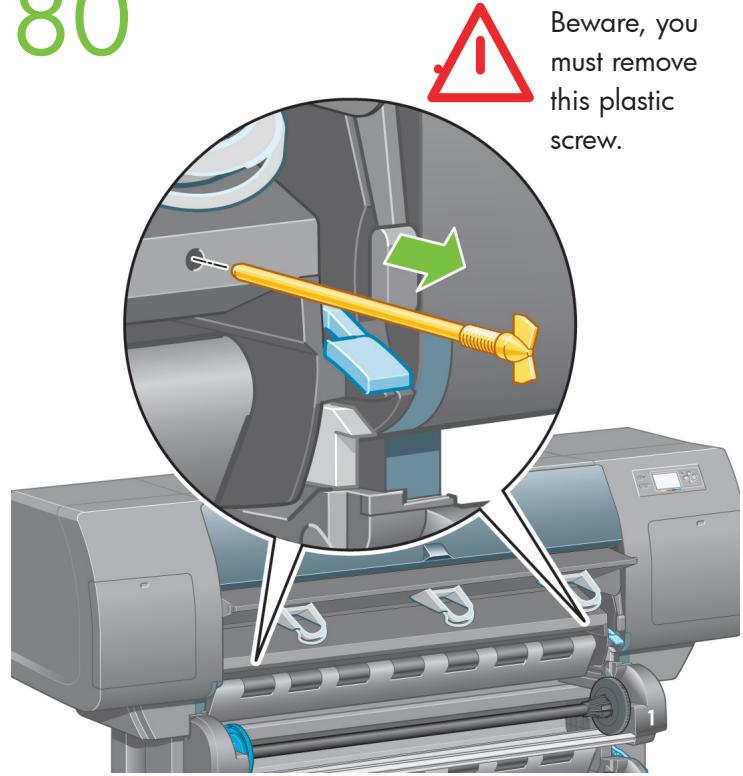
Remove the two yellow plastic screws from the right and left side of the paper feed.
81
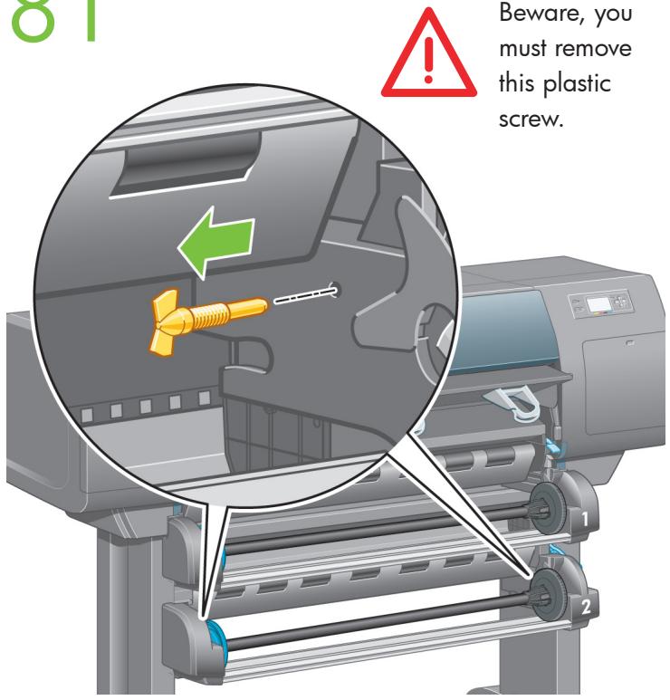
Remove the two yellow plastic screws from the left and right side of Drawer 2.
82
natural_image
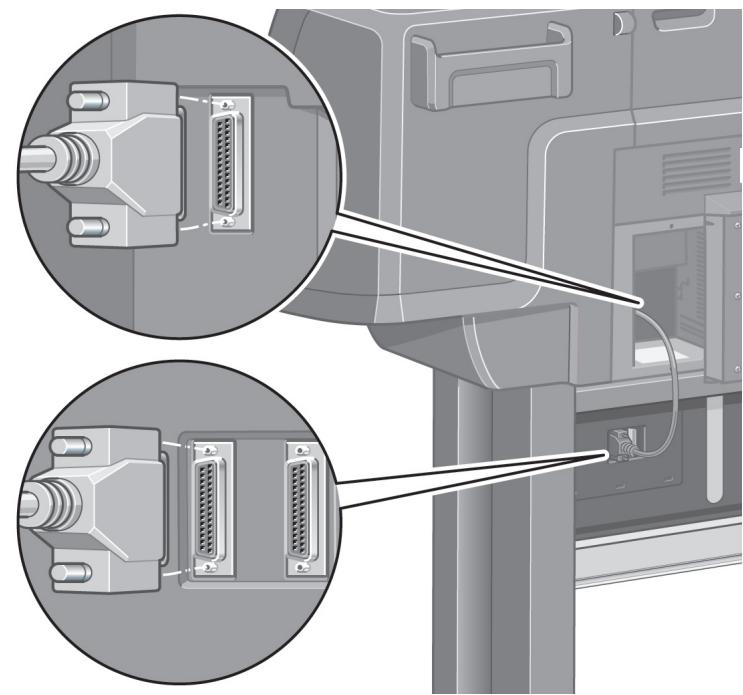
Diagram of a computer monitor with two close-up views showing internal components (no text or symbols)Using the cable supplied, connect the roll module to the printer.
83
natural_image
Illustration of two connected USB connectors with internal components (no text or symbols)A Fast Ethernet socket is provided for connection to a network.
Two FireWire sockets are provided for direct connection to computers.
84
natural_image
Illustration of a wall-mounted electrical socket connected to a plug, with a green arrow pointing to the socket (no text or symbols present)Plug the power cable into the rear of the printer, then plug the other end into the AC power outlet.
85
natural_image
Illustration of a hand inserting a plug into an electrical outlet with blue light rays (no text or symbols)Turn the power switch at the rear of the printer to the on position.
86
natural_image
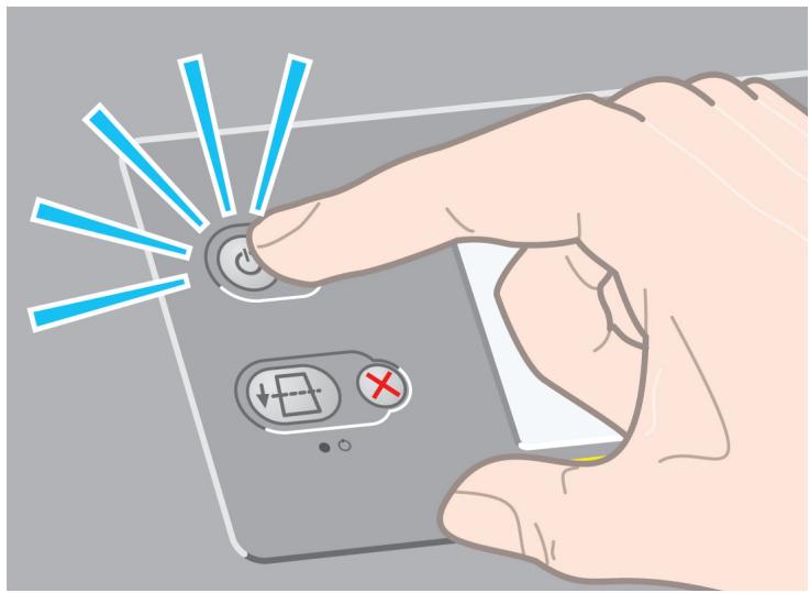
Illustration of a hand holding a smartphone with a button and control buttons, surrounded by blue light rays (no text or symbols)If the power light on the front panel remains off, press the Power key to switch on the printer.
Note: This printer is Energy Star compliant and can be left switched on without wasting energy. Leaving it on improves response time and overall system reliability.
87
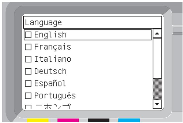
Wait until you see this message (\~10 minutes). Highlight your language using the Up and Down keys. Press the Select (,) key.
88
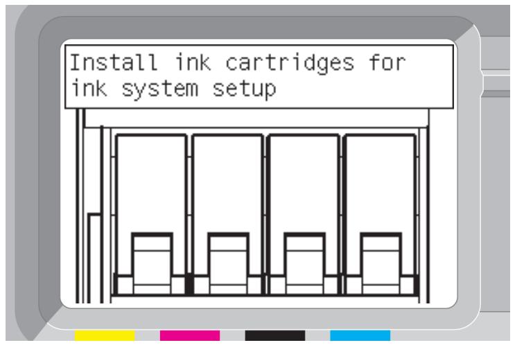
The front panel will now display how to install the ink supplies.
89
natural_image
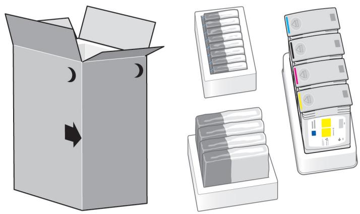
Illustration of a cardboard box with moon symbols and three separate compartments: one open, one closed, one stacked with boxes, and one partially filled with a yellow interface (no text or symbols)Remove the printheads, printhead cleaners, and ink cartridges from the consumables box.
90
natural_image
Illustration of a hand pressing down on a printer's screen (no text or symbols visible)Find the ink cartridge door, which is on the left side of the printer.
91
natural_image
Hand pressing down a computer screen with a green downward arrow (no text or symbols)Open the ink cartridge door.
92
natural_image
Hand pressing down a blue component with a green downward arrow (no text or symbols)To release the ink cartridge drawer, gently pull the blue handle down.
93
natural_image
Illustration of a hand inserting a blue plastic clip into an open gray printer holder, with a green arrow indicating the process (no text or symbols present)Slide the ink cartridge drawer out.
94
natural_image
Illustration of a hand inserting a device into a machine, with arrows indicating process flow (no text or symbols present)Place the ink cartridge onto the ink cartridge drawer. Note that there are marks on the drawer showing the correct location.
95
Position the ink cartridge at the rear of the drawer as indicated.
96
natural_image
Illustration of a hand inserting a card into an ATM machine with a green arrow indicating the process (no text or symbols present)Push the ink cartridge drawer back into the printer until it locks into position.
97
natural_image
Illustration of a printer printing into a rack with green arrows indicating process flow (no text or symbols)Following the same instructions, install the other three ink cartridges.
98
natural_image
Illustration of a hand inserting a CD into an ATM machine with a green upward arrow indicating growth (no text or symbols present)Close the ink cartridge door.
99
Wait (about a minute) until you see this front panel message.

100
natural_image
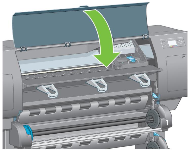
Illustration of a printer with a green arrow indicating the process, showing internal components and no text or symbols.Open the printer window.
101
natural_image
Illustration of a printer's internal structure showing internal components and a magnified view of the printer's interior (no text or symbols present)Remove the packing tape that is holding down the printhead carriage latch.
102
natural_image
Illustration of a hand pressing down on an electronic device casing with colored components and arrows indicating process flow (no text or symbols)Pull up and release the latch on top of the carriage assembly.
103
natural_image
Illustration of a hand inserting a component into a computer motherboard with a green upward arrow indicating motion (no text or symbols present)Lift up the cover. This will give you access to the setup printheads.
104
natural_image
3D rendering of a robotic arm with blue and pink components, no visible text or symbolsBefore removing the setup printheads, look at the window on top of each one and check that the printhead contains ink.
105
natural_image
Illustration of a hand inserting a component into a vehicle chassis, with a green arrow indicating the direction (no text or symbols present)To remove a setup printhead, lift up the blue handle.
106
natural_image
Illustration of a hand inserting a component into a computer motherboard, with a green upward arrow indicating the process (no text or symbols present)Using the blue handle, gently disengage the setup printhead from the carriage..
107
natural_image
Mechanical assembly diagram showing a hand operating a component with numbered parts and a green upward arrow indicating motion (no text or symbols present)Lift the setup printhead until it is released from the carriage assembly. Then remove the other setup printheads.
N
108
Remove the blue protective cap and the clear protective tape from the printhead.
109
natural_image
Close-up of a computer interface showing a hand adjusting a component with colored battery modules (no text or symbols visible)Lower all the printheads vertically into their correct positions.
110
natural_image
Illustration of a hand inserting into a mechanical device with a green downward arrow (no text or symbols)Seat the printheads slowly and carefully.
111
natural_image
Illustration of a hand inserting colored battery modules into a mechanical component (no text or symbols visible)Make sure the printheads are correctly seated. When all the printheads are installed, the front panel prompts, "Close printhead cover and window".
112
If "Reseat" is displayed on the front panel, check that the protective tape has been removed. Then try reseating the printhead more firmly. If the problem persists, refer to the Driver and Documentation CD.
113
natural_image
3D illustration of a computer interface with a hand inserting a component into a battery pack (no text or symbols visible)Close the carriage assembly cover.
114
natural_image
Illustration of a hand pressing a blue component into a computer motherboard, with a magnified inset showing the mechanical part (no text or symbols present)Make sure the latch engages correctly.
115
natural_image
Illustration of a printer with a green arrow indicating the process, showing internal components and no text or symbols.Close the printer window.

116
Please wait while the printer checks the printheads (\~1 minute).
117
Wait until you see this front panel message.
118
natural_image
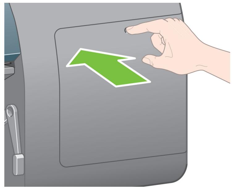
Illustration of a hand pressing a green arrow on a gray vehicle door panel (no text or symbols)Press the printhead cleaner door, which is on the right side of the printer.
119
natural_image
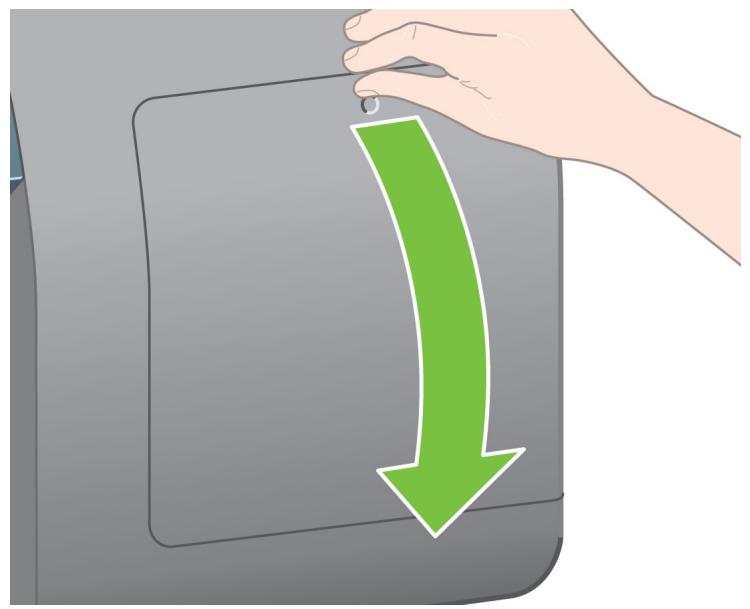
Hand placing a green arrow into a gray rectangular object, symbolizing a process or action (no text or symbols present)Open the printhead cleaner door.
120
Insert the printhead cleaner into the slot of the correct color.
121
Push the printhead cleaner in and down until it clicks into place.
122
Insert the other seven printhead cleaners into the correct slots.
123
natural_image
Illustration of a hand inserting into a printer into a rack with color-coded compartments (no text or symbols)Close the printhead cleaner door.
P
124
Wait until you see this front panel message. Press the Select (,) key
128
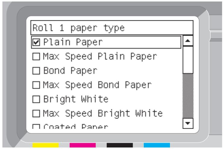
The front panel displays the above. Highlight the paper type you have loaded and press the Select (s) key.
125
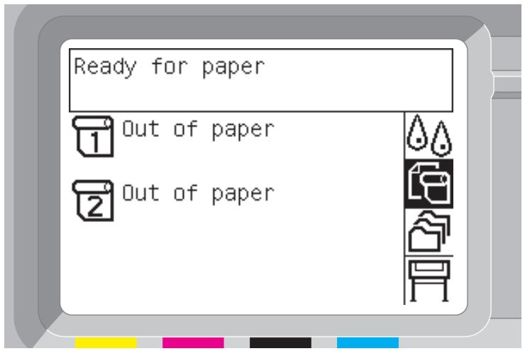
To load the paper roll from Drawer 1 into the printer. From the front panel, highlight the Paper icon and press the Select (,) key.
129
natural_image
Illustration of a printer with two green arrows indicating motion or flow, no text or symbols presentUsing two hands, pull out Drawer 1.
126
From the front panel, highlight 'Paper load' and press the Select (,) key.
130
natural_image
Illustration of a printer with two green arrows indicating parts of the mechanism (no text or symbols present)Remove spindle from Drawer 1.
127
The front panel displays the above. Highlight 'Load roll 1' and press the Select (,) key.

131
natural_image
3D mechanical assembly diagram showing a blue circular component inserted into a gray cylindrical housing, with no visible text or symbols.Shown above is one of the core adaptors supplied. Use these when the roll core is of a larger diameter.
132
natural_image
3D illustration of a blue plastic device with a green arrow indicating transformation from a circular component to a cylindrical pipe (no text or symbols)Remove the blue-colored stop from the left end of the spindle. Keep the spindle horizontal.
133
natural_image
Illustration of two paper rolls with a red prohibition symbol (no text or labels)Slide the roll of paper that came with your printer onto the spindle. Make sure the paper is oriented exactly as shown.
134
natural_image
Diagram showing a mechanical component with a green arrow indicating motion, no text or symbols presentPush the black right-hand stop onto the roll. Make sure it is correctly seated.
135
natural_image
Illustration of a blue plastic container being inserted into a cylindrical roller, with a green arrow indicating the process (no text or symbols present)Put the blue-colored stop onto the spindle.
136
natural_image
Diagram showing a blue plastic component being processed by a camera lens, with a magnified inset highlighting the structural detail (no text or symbols present)Push the blue left-hand stop onto the roll. Make sure it is correctly seated.
137
natural_image
Illustration of a hand pressing a blue circular device with a small component on top (no text or symbols visible)As shown above, hold the spindle assembly using the blue and black stops.
138
natural_image
Illustration of a printer's paper roll system with green arrows indicating motion (no text or symbols)With the blue stop on the left, lower the spindle into Drawer 1.
R
139
natural_image
Mechanical component diagram showing a green arrow indicating rotational motion (no text or symbols present)Lift the blue lever on Drawer 1. This is located on the right-hand side of the printer and above Drawer 1.
140
natural_image
Illustration of a printer printing a sheet of paper with green arrows indicating motion or flow (no text or symbols present)Feed the paper onto the platen of Drawer 1. Align the paper with the middle blue line on the right side of the platen.
141
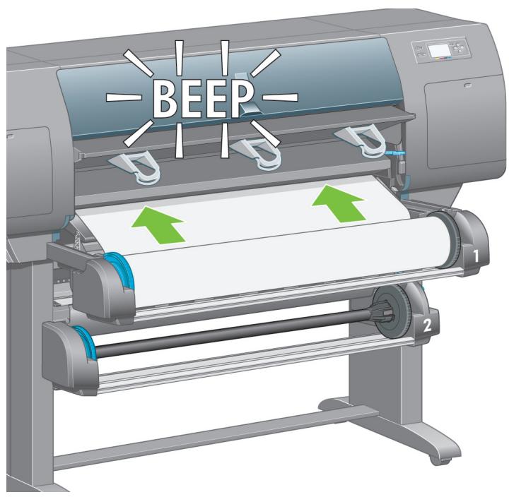
Stop feeding the paper when the printer beeps.
142
natural_image
Mechanical assembly diagram showing a blue pipe passing through a housing with a green circular arrow indicating motion (no text or symbols)Lower the blue lever for Drawer 1.
143
natural_image
Illustration of a printer with paper roll and green directional arrows indicating motion (no text or symbols)Push in Drawer 1.
144
natural_image
Cross-sectional diagram of a mechanical component with green directional arrows indicating flow or movement (no text or symbols)Using the stops, carefully wind the excess paper back on to the spindle.
145

Select the roll length if known.
146
To load the roll paper from Drawer 2: from the front panel, highlight the Paper icon and press the Select (,) key.
147
From the front panel, highlight 'Paper load' and press the Select (,) key.
148
The front panel displays the above. Highlight 'Load roll 2' and press the Select (s) key.
149
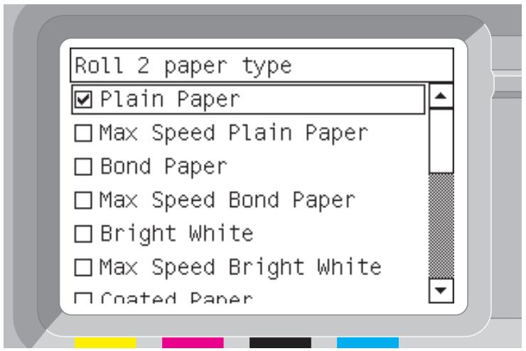
The front panel displays the above. Highlight the paper type you have loaded and press the Select (,) key.
150
natural_image
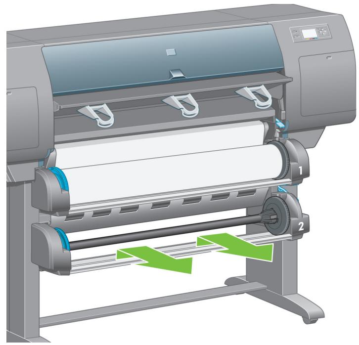
Illustration of a printer with paper roll and green directional arrows indicating motion (no text or symbols)Using two hands, pull out Drawer 2.
151
natural_image
Illustration of a printer with two green arrows indicating directional movement (no text or symbols present)Remove the spindle from Drawer 2.
152
Load the spindle using the same procedure as described by points 131 to 137.
153
natural_image
Illustration of a printer with paper roll and green arrows indicating motion or assembly (no text or symbols)With the blue stop on the left, lower the spindle into Drawer 2.
154
natural_image
Diagram of a mechanical device with a blue conveyor belt and green directional arrow indicating motion (no text or symbols)Lift the blue lever on Drawer 2. This is located on the right-hand side of the printer and under Drawer 1.
155
natural_image
Illustration of a printer with two green arrows indicating directional motion (no text or symbols present)Feed the paper onto the platen of Drawer 2. Align the paper with the blue line on the right side of the platen.
T
156
Stop feeding the paper when the printer beeps.
157
natural_image
Mechanical assembly diagram showing a component with a green arrow indicating rotation or motion (no text or symbols present)Lower the blue lever for Drawer 2.
158
natural_image
Illustration of a printer with two green arrows indicating printing or printing process (no text or symbols present)Using two hands, push in Drawer 2.
159
natural_image
Cross-sectional diagram of a mechanical component with green and blue directional arrows indicating motion or flow (no text or symbols)Using the stops, carefully wind the excess paper back on to the spindle.
160
natural_image
Diagram of a computer interface showing cable routing and a green arrow indicating a specific component (no text or symbols present)Pass the LAN cable through the hook at the rear of the printer.
161
natural_image
Diagram of a computer interface showing an inserted D-sub connector and cable connections (no text or symbols present)The roll module provides an extra socket to connect an optional accessory.
Caution: do not attempt to use this socket for any other purpose.
162
flowchart
graph TD
    A["Printer"] --> B["Server"]
    B --> C["PC, Macintosh or workstation"]
    D["PC, Macintosh or workstation"] --> E["Computer"]
Your printer can be connected to a computer directly or to one or more computers via a network.
163
natural_image
Illustration of various metal rack arrangements and a pulley system (no text or symbols)Locate all the parts for the bin assembly. The screwdriver is the same one used to fix the roll module to the printer stand.

164
natural_image
3D illustration of a shopping cart with wheels and a basket, no text or symbols presentLay one end frame on the floor. Hold one cross frame vertically with the angled part located at the top of the end frame. The cross frame must be fixed on to the inside of the shortest leg of the end frame.
165
natural_image
Diagram of a mechanical structure with green arrows indicating motion or force direction (no text or symbols)Fix the cross frame to the end frame using two screws.
166
natural_image
Diagram showing a mechanical assembly with a magnified view of a bolt inserted into a cylindrical component, mounted on a metal rack (no text or symbols present)Turn the bin assembly into a horizontal position. Attach the short leg of the second end frame to the cross frame using two screws.
167
Attach the second cross frame to the bin assembly using four screws. Please note that this cross frame is mounted on the outside of the end frames.
168
natural_image
Diagram of a metal rack with green arrows indicating movement or force, showing structural changes (no text or symbols present)Attach one end of the loop on to the cross frame.
169
natural_image
Illustration of a metal rack with green arrows indicating downward motion, plus an inset showing a detailed view of the rack structure (no text or symbols)Attach the other end of the loop on to the cross frame. Using the same method, attach the other 5 loops.
170
natural_image
Illustration of a large printer with paper roll and metal rack, showing no text or symbols on the device itself.Locate the bin against the printer.

Now you have completed the assembly of your printer. The following pages describe how to configure your computer for successful printing.
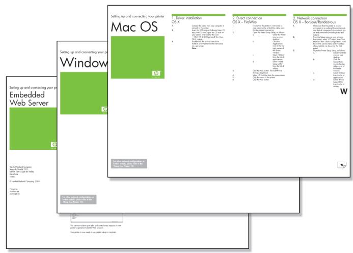
Setting up and connecting your printer
Mac OS

1. Driver installation
OS X
- Connect the cable from your computer or network to the printer.
- Insert the Drivers and Documentation CD into your CD drive, open the CD icon on your screen, and look for this icon:
• 'OS X HP DJ 4500ps Install' - Double-click the icon to launch the installer, and then follow the instructions on your screen.
- When the printer driver has been installed, the HP Printer Setup Assistant will start automatically, to set up a network or direct connection to your printer. Again, follow the instructions on your screen.
- When the HP Printer Setup Assistant has finished, remove the CD from the CD-ROM drive.
Setting up and connecting your printer
Windows

Network connection Windows
A network connection is the best way to share your printer with your team.
- Make sure that the printer and the computer are both connected to the network.
- Go to the printer's front panel and highlight the Setup icon.
- The front panel will display some information, including the printer's IP address. Make a note of the IP address.
-
Insert the Drivers and Documentation CD into your CD drive. If the CD does not autorun, run the START.EXE program in the root folder of the CD.
-
Click the Install button.
-
Follow the instructions on your screen to set up the printer. The following notes will help you to understand the screens and make appropriate choices:
-
When asked how the printer is connected, choose 'Connected via the network'.
- Select your printer from the list. If you have more than one HP Designjet printer, use the IP address that you noted earlier to confirm that you have selected the correct printer.
-
When the network settings of the selected printer are displayed, check that they are correct.
-
Now turn the page and go to the Embedded Web Server information.
Direct connection Windows
A direct connection using FireWire (IEEE 1394) or USB may be faster than a network connection, but the cable is limited in length and it is more difficult to share the printer.
Please note that a USB connection requires an optional accessory card.
- Do not connect the computer to the printer yet. You must first install the printer driver software on the computer, as follows.
- Insert the Drivers and Documentation CD into your CD drive. If the CD does not autorun, run the START.EXE program in the root folder of the CD.
- Click the Install button.
- Follow the instructions on your screen to set up the printer. The following notes will help you to understand the screens and make appropriate choices:
- When asked how the printer is connected, choose 'Connected directly to this computer'.
- When prompted to do so, connect your computer to the printer, using a FireWire or USB cable. Ensure that the printer is switched on.
- Your printer is now ready to use, printer setup is complete.
Setting up and connecting your printer
Embedded Web Server

Hewlett-Packard Company
Avenida Graells, 501
© Hewlett-Packard Company, 2005
Printed in
Imprimé en
Stampato in
Embedded Web Server Windows and Mac OS
- Open a Web browser on any computer with an Internet connection, and enter the IP address of your printer (available only if you have a network connection to the printer).
- Check that the Embedded Web Server opens and you can see information about your printer similar to that shown below.
Supplies window

bar
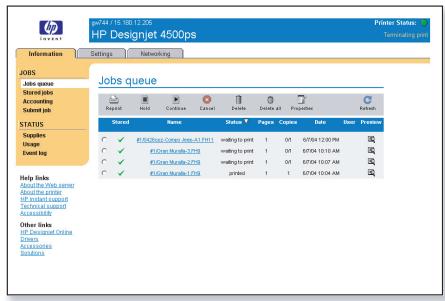
HP Designjet 4500ps | Category | Paper Type | Type | Width | Length | Buy now | | :--- | :--- | :--- | :--- | :--- | :--- | | | No paper loaded | - | - | - | - | | | Paper | - | - | - | - | | | Ink cartridges | - | - | - | - | | | Ink cartridge Status Ink level (ml) Capacity Type Warranty status HP Order Information | OK | 204 225 In warranty HP No 90 (C5084A) | - | - | | | Yellow Magenta OK 395 400 In warranty HP No 90 (C5063A) | OK | 395 400 In warranty HP No 90 (C5063A) | - | - | | | Black Okn 379 400 In warranty HP No 90 (C5058A) | OK | 379 400 In warranty HP No 90 (C5058A) | - | - | | | Cyan Okn 206 225 In warranty HP No 90 (C5060A) | OK | 206 225 In warranty HP No 90 (C5060A) | - | - | | | Printheads and Cleaners | - | - | - | - | | | Printhead Printhead status Warranty status Cleaner status | - | - | - | - | | Yellow 1 OK In warranty OK | - | - | - | - | - | | Yellow 2 OK In warranty OK | - | - | - | - | - | | Magenta 3 OK In warranty OK | - | - | - | - | - | | Magenta 4 OK In warranty OK | - | - | - | - | - | | Black 5 OK In warranty OK | - | - | - | - | - | | Black 6 OK In warranty OK | - | - | - | - | - | | Cyan 7 OK In warranty OK | - | - | - | - | - | | Cyan 8 OK In warranty OK | - | - | - | - | - | Done Local intranetJobs queue window
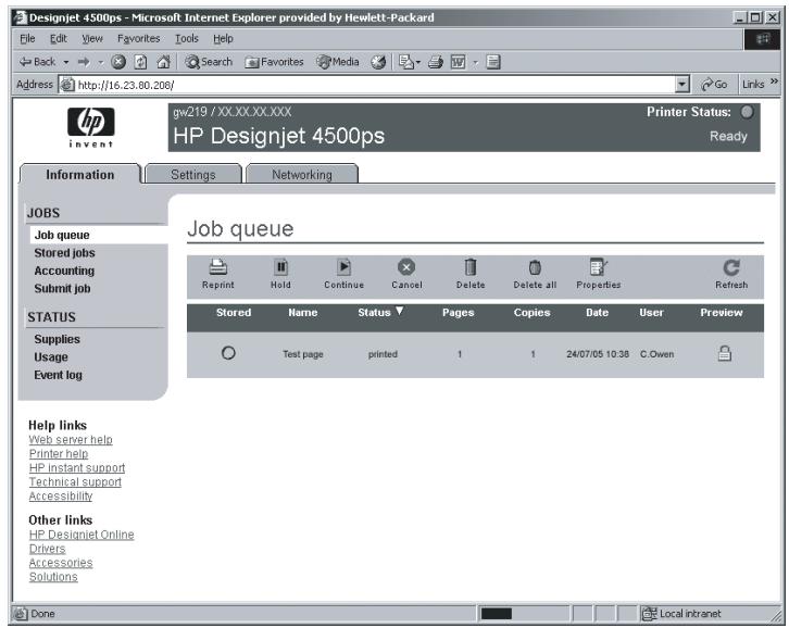
You can now submit print jobs and control many aspects of your printer's operation from the Web browser.
Your printer is now ready to use, printer setup is complete.